NSZ/NDZ Indoor Split Installation Manual Geothermal/Water Source Indoor Split Heat Pump 2 to 6 Tons Single Speed 2 to 6 Tons Dual Capacity Installation Information Water Piping Connections Hot Water Generation Connections Electrical Startup Procedures Troubleshooting Preventive Maintenance IM1003SN 08/10
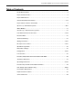
NSZ/NDZ INDOOR SPLIT INSTALLATION MANUAL Table of Contents Model Nomenclature . . . . . . . . . . . . . . . . . . . . . . . . . . . . . . . . . . . . . . . . . . . . . . . . . . . . . . . . . . . 4 Physical Characteristics . . . . . . . . . . . . . . . . . . . . . . . . . . . . . . . . . . . . . . . . . . . . . . . . . . . . . . . . . 4 Physical Dimensions . . . . . . . . . . . . .
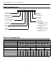
NSZ/NDZ INDOOR SPLIT INSTALLATION MANUAL Model Nomenclature 1 2 3 4-6 7 8 9 10 11 N D Z 049 A 1 1 A C Model Type N = Envision Coax Options C = Copper N = Cupronickel Compressor Type D = Dual Capacity S = Single Speed Future Option A = Standard Cabinet Configuration Z = Indoor Split Hot Water Option 0 = No Hot Water Generator, No IntelliStart 1 = Hot Water Generator with factory installed pump, No IntelliStart 3 = No Hot Water Generator, IntelliStart 4 = Hot Water Generator with facto
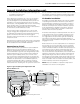
NSZ/NDZ INDOOR SPLIT INSTALLATION MANUAL Physical Dimensions B C A J H M L K E F G D Model Height Width Depth Water In Water Out Service Valve Liquid Gas HWG In HWG Out Low Voltage External Pump Line Voltage A B C D E F G H J K L M 022-030 19.25 22.50 26.50 1.93 6.93 8.44 11.55 13.43 16.43 8.55 10.30 11.80 038-072 21.25 25.50 31.50 2.21 7.21 9.21 12.14 15.83 18.83 7.71 9.46 10.96 Dimensions are in inches.
NSZ/NDZ INDOOR SPLIT INSTALLATION MANUAL General Installation Information Safety Considerations Duct System All blower coil units/air coils must be installed as specified by the manufacturer’s installation instructions; however, the following recommendations should be considered to minimize noise and service problems. WARNING: Before performing service or maintenance operations on a system, turn off main power switches to the indoor unit. If applicable, turn off the accessory heater power switch.
NSZ/NDZ INDOOR SPLIT INSTALLATION MANUAL General Installation Information cont. • • line sets should be insulated with a minimum of 1/2 in. closed cell insulation. All exterior insulation should be painted with UV resistant paint or covering to ensure long insulation life.
NSZ/NDZ INDOOR SPLIT INSTALLATION MANUAL General Installation Information cont. Dual Fuel Systems In add-on Envision Split applications, the coil should be located in the supply side of the furnace to avoid condensation damage to the furnace heat exchanger. A high temperature limit should be installed upstream of the coil to de-energize the compressor whenever the furnace is operating. Without this switch, the Envision Split will trip out on high pressure.
NSZ/NDZ INDOOR SPLIT INSTALLATION MANUAL General Installation Information cont. Air Handler Sizing Selection The Envision Air Handlers are designed for R410a refrigerant and should be matched with Envision Split series compressor section according to the table below.
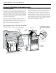
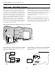
NSZ/NDZ INDOOR SPLIT INSTALLATION MANUAL Open Loop - Well Water Systems Typical open loop piping is shown below. Always maintain water pressure in the heat exchanger by placing water control valves at the outlet of the unit to prevent mineral precipitation. Use a closed bladder type expansion tank to minimize mineral formation due to air exposure.
NSZ/NDZ INDOOR SPLIT INSTALLATION MANUAL Open Loop - Well Water Systems cont. Solenoid Wiring Water control valves draw their power directly from a unit’s 24V transformer and can overload and possibly burn out the transformer. Check total VA draw of the water valve and ensure that it is under 15 VA. Water Quality In ground water situations where scaling could be heavy or where biological growth such as iron bacteria will be present, a closed loop system is recommended.
NSZ/NDZ INDOOR SPLIT INSTALLATION MANUAL Closed Loop - Ground Source Systems Multiple Units on One Flow Center Note: For closed loop systems with antifreeze protection, set SW2-2 to the “loop” position (see DIP Switch Settings table). When two units are connected to one loop pumping system, pump control is automatically achieved by connecting the SL terminals on connector P2 in both units with 2-wire thermostat wire. These terminals are polarity dependant (see Figure 8).
NSZ/NDZ INDOOR SPLIT INSTALLATION MANUAL Hot Water Generator Connections Note: Under certain conditions, Envision dual capacity units operate with very low refrigerant discharge temperatures, producing little or no water heating capability. This scenario occurs when the unit is operating with cold entering source water (loop or well). Allowing the hot water generator pump to operate during these conditions actually removes heat from the DHW circulating through the unit.
NSZ/NDZ INDOOR SPLIT INSTALLATION MANUAL Hot Water Generator Connections cont. Plumbing Installation Hot Water Generator Startup 1. 1. 2. 3. Inspect the dip tube in the water heater cold inlet for a check valve. If a check valve is present it must be removed or damage to the hot water generator circulator will occur. 2. Remove drain valve and fitting. 3. Thread the 3/4-inch NPT x 3-1/2-inch brass nipple into the water heater drain port. 4.
NSZ/NDZ INDOOR SPLIT INSTALLATION MANUAL Electrical Data Be sure the available power is the same voltage and phase as that shown on the unit serial plate. Line and low voltage wiring must be done in accordance with local codes or the National Electric Code, whichever is applicable. See unit electrical data for fuse or circuit breaker sizing information.
NSZ/NDZ INDOOR SPLIT INSTALLATION MANUAL Wiring Schematics Dual Capacity Split Wiring Schematic - 208-230/60/1 Notes: S C 1 - 24V Accessory relay (see SW2-3 for description of operation) 2 - This Switch allows the unit to down stage with the t-stat when OFF and finish on second stage when ON. Finish second stage reduces stage changing in recip dual capacity compressors and should be ON for unzoned Dual Cap E-Series or Premier 2 speed units.
NSZ/NDZ INDOOR SPLIT INSTALLATION MANUAL Wiring Schematics cont. Single Speed Split Wiring Schematic - 208-230/60/1 Notes: S C 1 - 24V Accessory relay (see SW2-3 for description of operation) 2 - This Switch allows the unit to down stage with the t-stat when OFF and finish on second stage when ON. Finish second stage reduces stage changing in recip dual capacity compressors and should be ON for unzoned Dual Cap E-Series or Premier 2 speed units.
NSZ/NDZ INDOOR SPLIT INSTALLATION MANUAL Microprocessor Control Startup Diagnostics The unit will not operate until all the inputs and safety controls are checked for normal conditions. At first powerup, a four-minute delay is employed before the compressor is energized. The Envision control board allows all inputs and outputs to be displayed on the LEDs for fast and simple control board diagnosis. (Refer to the Field Selection DIP Switch SW2-1.
NSZ/NDZ INDOOR SPLIT INSTALLATION MANUAL Microprocessor Control cont. Heat, 3rd Stage (Y1,Y2,W) Single-Speed Units Lockout Conditions The first stage of resistance heat is energized 10 seconds after “W” input, and with continuous 3rd stage demand, the additional stages of resistance heat engage 90 seconds after the first stage. During lockout mode, the appropriate unit and thermostat lockout LEDs will illuminate. The compressor, loop pump, hot water pump, and accessory outputs are de-energized.
NSZ/NDZ INDOOR SPLIT INSTALLATION MANUAL Microprocessor Control cont. Compressor Monitoring/Comfort Alert pressor alerts are displayed on the module by flashing the yellow Alert LED a specific number of times consecutively followed by a pause, and then repeated. The number of consecutive flashes or “Flash Code” correlates to a specific abnormal condition. The red “TRIP” LED means there is a thermostat demand signal “Y” present but the compressor is not running.
NSZ/NDZ INDOOR SPLIT INSTALLATION MANUAL Microprocessor Control cont. Thermostat Displays thermostat can be configured to show either lockout text or lockout codes. Fault Flash When using a TA32W01 or TP32W02 thermostat and SW28 is in the pulsing “L” position, FaultFlash will enable a user to view the thermostat and count the fault indicator flashes to determine the lockout condition the unit is experiencing. The LED board on the front of the unit will display all lockouts.
NSZ/NDZ INDOOR SPLIT INSTALLATION MANUAL Operation Logic Data OPERATION LOGIC HEATING STG1 STG2 COOLING STG3 EMERG STG1 FAN ON STG2 SL1 - IN ON SL2 - IN ON SINGLE SPEED UNITS Compressor On On On Off On On - - - Rev Valve Off Off Off Off On On - - - Loop Pump On On On Off On On - On - DHW Pump On Off Off Off On On - - - Secondary 1- Out On On On Off On On - - - Emerg LED Off Off Off On Off Off Off - - T-Stat Signal Y1 Y1, Y2 Y1, Y2, W
NSZ/NDZ INDOOR SPLIT INSTALLATION MANUAL Refrigeration The Envision series comes with a holding charge. The charge must be adjusted in the field based on performance. Refrigeration piping on the split consists of installing a brazed copper line set between the blower coil unit and the unit’s split compressor section. To select the proper tube diameters for the installation, refer to the Line Set Sizes table. Line sets over 60 feet long are not recommended because of oil return and pressure drop problems.
NSZ/NDZ INDOOR SPLIT INSTALLATION MANUAL Refrigeration cont. Leak Testing After initial charge, the system should be operated and the system subcooling and superheat verified to the Unit Operating Parameters table. The refrigeration line set must be pressurized and checked for leaks before purging and charging the unit. To pressurize the line set, attach refrigerant gauges to the service ports and add an inert gas (nitrogen or dry carbon dioxide) until pressure reaches 60 to 90 PSIG.
NSZ/NDZ INDOOR SPLIT INSTALLATION MANUAL Refrigeration cont. Warning: There are 8 total (360°) turns on the superheat adjustment stem from wide open to fully closed. When adjusting the superheat stem clockwise (superheat increase) and the stop is reached, any further clockwise turning adjustment will damage the valve. Determining Subcooling 1. 2. 3. 4. Measure the temperature of the liquid line on the small refrigerant line (liquid line) just outside the split cabinet.
NSZ/NDZ INDOOR SPLIT INSTALLATION MANUAL Pressure/Temperature Conversion Chart for R-410A PRESSURE (PSIG) TEMP °F PRESSURE (PSIG) 60 62 64 66 68 70 72 74 76 78 80 82 84 86 88 90 92 94 96 98 100 102 104 106 108 110 112 114 116 118 120 122 124 126 128 130 132 134 136 138 140 142 144 146 148 150 152 154 156 158 160 162 164 166 168 170 172 174 176 178 8.5 9.9 11.2 12.5 13.8 15.1 16.3 17.5 18.7 19.8 21.0 22.1 23.2 24.3 25.4 26.5 27.5 28.6 29.6 30.6 31.6 32.6 33.5 34.5 35.4 36.4 37.3 38.2 39.1 40.0 40.9 41.
NSZ/NDZ INDOOR SPLIT INSTALLATION MANUAL Thermistor Resistance Thermistor Temperature (°F) Resistance in Ohms 78.5 9230 -10007 77.5 9460 - 10032 76.5 9690 - 10580 75.5 9930 - 10840 33.5 30490 - 32080 32.5 31370 - 33010 31.5 32270 - 33690 30.5 33190 - 34940 1.5 79110 - 83750 0.5 81860 - 86460 0.
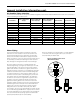
NSZ/NDZ INDOOR SPLIT INSTALLATION MANUAL Operating Parameters cont. NDZ026 thru NDZ072 (with NAH Series Air Handler) First Stage Operation Entering Water Temp °F 50 70 90 Entering Water Temp °F 30 50 70 Water Flow GPM/Ton 1.5 3.0 1.5 3.0 1.5 3.0 Water Flow GPM/Ton 1.5 3.0 1.5 3.0 1.5 3.
NSZ/NDZ INDOOR SPLIT INSTALLATION MANUAL Pressure Drop and Recommended Flow Rates Single Speed Model 022 030 036 042 048 060 070 GPM 3 4.5 6 8 4 6 8 10 5 7 9 12 5 8 11 14 6 9 12 16 9 12 15 20 12 15 18 24 30°F 0.9 1.7 2.8 4.7 1.5 3.0 5.1 7.7 1.0 2.1 3.6 6.3 0.8 2.1 4.2 7.6 1.1 2.3 3.9 6.7 2.4 3.9 5.7 9.5 3.0 4.4 6.0 9.7 Dual Capacity Pressure Drop (psi) 50°F 70°F 90°F 0.9 0.8 0.7 1.6 1.5 1.4 2.7 2.5 2.3 4.4 4.1 3.9 1.4 1.3 1.2 2.8 2.7 2.5 4.8 4.5 4.2 7.2 6.8 6.3 1.0 0.9 0.8 1.9 1.8 1.7 3.3 3.0 2.
NSZ/NDZ INDOOR SPLIT INSTALLATION MANUAL Unit Startup Before Powering Unit, Check The Following: • • • • • • • • • • • • • • • • 10. Initiate a control signal to place the unit in the heating mode. Heating set point must be set above room temperature. 11. First stage heating will energize after a time delay. 12. Check the temperature of both the supply and discharge water (see Operating Parameters tables). 13.
NSZ/NDZ INDOOR SPLIT INSTALLATION MANUAL Unit Startup/Troubleshooting Heating Cycle Analysis Measure suction temperature here at TXV bulb in cooling modes. Measure suction temperature here at TXV bulb in heating modes.
NSZ/NDZ INDOOR SPLIT INSTALLATION MANUAL Troubleshooting Standard Microprocessor Controls 4. If control responds improperly: • Ensure that component being controlled is functioning (compressor, blower, reversing valve, etc.). • Ensure that wiring from control to the component is functioning (refer to the LED Definition table below and use the diagnostic outputs mode). • If steps above check properly, replace unit control. To check the unit control board for proper operation: 1.
NSZ/NDZ INDOOR SPLIT INSTALLATION MANUAL Preventative Maintenance Water Coil Maintenance Condensate Drain 1. In areas where airborne bacteria produce a slime in the drain pan, it may be necessary to treat chemically to minimize the problem. The condensate drain can pick up lint and dirt, especially with dirty filters. Inspect twice a year to avoid the possibility of overflow. 2. Keep all air out of the water.
NSZ/NDZ INDOOR SPLIT INSTALLATION MANUAL Service Parts List Single Speed Split Units Compressor 022 030 036 042 Refrigeration Components 026 038 049 064 072 Run Capacitor 16P002-18 16P002-20 Sound Jacket 16P002-21 92P504A16 Power Harness Coax 33P609-01 Reversing Valve 33P506-04 Hot Water Generator Pump Comfort Alert Contactor 11P781-01 N/A 11P782-01 36P509-01 62P542B01 33P609-03 62P543B01 33P609-05 36P509-02 36P509-01 62P555-01 62P504C01 62P542B01 62P543B01 33P609-06 33P50
Manufactured by WaterFurnace International, Inc. 9000 Conservation Way Fort Wayne, IN 46809 www.waterfurnace.com IM1003SN 08/10 Product: Type: Size: Document: Envision Series NSZ/NDZ Geothermal/Water Source Indoor Split Heat Pump 2-6 Ton Single Speed 2-6 Ton Dual Capacity Installation Manual ©2010 WaterFurnace International, Inc., 9000 Conservation Way, Fort Wayne, IN 46809-9794.