WARNING This manual contains information on limitations regarding product use and function and information on the limitations as to liability of the manufacturer. The entire manual should be carefully read. NT9010 v 1.1A Installation Guide DLS-3 v1.
Limited Warranty Digital Security Controls Ltd. warrants the original purchaser that for a period of twelve months from the date of purchase, the product shall be free of defects in materials and workmanship under normal use. During the warranty period, Digital Security Controls Ltd. shall, at its option, repair or replace any defective product upon return of the product to its factory, at no charge for labour and materials.
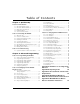
Tab l e o f C o n t e n t s Chapter 1: Quick Set Up Section 1.1: Introduction 1.1.1 1.1.2 1.1.3 1.1.4 1.1.5 About the NT9010 System ................................. 1 About the NT9010 Manual Set .......................... 1 Main system Specifications ................................. 2 Additional Devices ............................................. 3 Peel-off Instruction Labels .................................. 4 Section 1.2: Installing The NT9010 1.2.1 1.2.2 1.2.3 1.2.4 1.2.5 1.2.6 1.2.7 1.2.8 1.2.
WARNING Please Read Carefully N o te to In stal ler s This warning contains vital information. As the only individual in contact with system users, it is your responsibility to bring each item in this warning to the attention of the users of this system. Sy st em Fai lur es This system has been carefully designed to be as effective as possible. There are circumstances, however, involving fire, burglary, or other types of emergencies where it may not provide protection.
Chapter 1: Quick Set Up Section 1.1: Introduction 1.1.1 About the NT9010 System The NT9010 is a full-featured, wireless security system. It has been designed for fast and easy installation, in household fire, burglary and home health care applications. The NT9010 system is made up of the following components: • A main control unit • Up to 32 wireless detectors and panic pendants (total) • You can also add up to 16 wireless keys.
Chapter 1: Quick Set Up ☛ Programming Worksheets This manual is used to record your zone choices and other programming for the system. NOTE: Keep this manual in a safe place for future reference. ☛ User’s Guide The User’s Guide provides easy to follow instructions for NT9010 users. This Guide contains instructions on turning the system on or off, dealing with alarms and emergencies, using advanced functions, fire safety, and how to replace wireless device batteries.
Se cti o n 1.
Chapter 1: Quick Set Up WLS914-433 Dual PIR Wireless Motion Detector The dual PIR wireless motion detector can be used to provide wireless space protection. The unit comes with four AA batteries. WLS925L-433 Mini Wireless Universal Transmitter The WLS925L-433 wireless universal transmitter is a smaller transmitter that can be used for door and window contacts. The unit comes with one Lithium battery and has built-in contacts.
Section 1.2: Installing The NT9010 Please read this section to get an overall understanding of the steps involved in installing the NT9010 system. Carefully work through each step. This will help to reduce problems and to reduce the overall installation time required. 1.2.1 Out of the Box Check the contents label on the outside of the package to ensure all components have been received. 1.2.2 Create an Installation Plan Draw a rough sketch of the building.
Chapter 1: Quick Set Up To remove the backplate from the NT9010: 1. Remove the plastic screw from the top of the NT9010 unit (see Figure 1). Keep the screw in a safe location so that you can replace it later. 2. Insert a flathead screwdriver in the slots shown in Figure 1. Twist the screwdriver so that the backplate separates from the plastic housing. 3. Pull the top of the backplate away from the NT9010. 4. Unhook the backplate from the bottom of the NT9010.
S ec tio n 1 .2: In s tal lin g T h e N T9 01 0 NOTE: Do not connect the transformer to a power supply until all other wiring is complete. NOTE: If you remove power from the unit (AC and battery), you must wait at least 10 seconds before reapplying power.
Chapter 1: Quick Set Up Single End Of Line (EOL) Resistors To enable system detection of single end of line resistors, programming section [013], option [1] must be OFF. NOTE: This option should be selected if either Normally Closed (NC) or Normally Open (NO) detection devices or contacts are being used. End of Line Resistors . . . . . . . . . . . . . . . . . . . . . . . . . . . .
S ec tio n 1 .2: In s tal lin g T h e N T9 01 0 If there is a Remote Sounder on the system and it does not report a supervisory signal within 30 seconds, a “Service Required” trouble will be generated, and a “Remote Sounder Trouble” event will be logged in the buffer. See also 2.3.13 Talk/Listen-in Programming on page 46. Local Annunciation . . . . . . . . . . . . . . . . . . . . . . . . . . . . . Section [017], Option [4] Remote Annunciation . . . . . . . . . . . . . . . . . . . . . . . . . . .
Chapter 1: Quick Set Up You can use the Forward (Playback) button to advance to the next section in Flash Programming, and the Backward (Record) button to return to the previous section. 5. Be sure to record all the zone serial numbers and your programming choices in the NT9010 Programming Worksheets. Here are some notes about system programming done through Flash Programming.
S ec tio n 1 .2: In s tal lin g T h e N T9 01 0 [87] Delayed 24 Hour Fire (Wireless): If this zone is violated (e.g. the smoke detector senses smoke), the alarm will immediately sound, but the alarm communication to the central station will be delayed for 30 seconds. If during the 30 second delay the user presses the [#] key, the alarm and communicator will be delayed an additional 90 seconds. This provides time for a user to correct the problem.
Chapter 1: Quick Set Up NOTE: You must accept a label to exit this section. If you choose F for a custom label, then you must create your own label using the Audio Label Library and accept it. NOTE: If you chose one of the audio labels, section [001] to [005] (#3 above) and there is no audio label recorded, the label will default to “zone X” where “X” is the zone number of the device enrolled. When the label is recorded in section [807], [701] to [705] it will be used.
S ec tio n 1 .2: In s tal lin g T h e N T9 01 0 1.2.9 Deleting Wireless Devices To remove a wireless device from the system, you will need to use the advanced programming sections. 1. Press [✱][8], then enter the Installer’s code. The default Installer’s code is [5555]. 3. When prompted, press [2] to go to advanced programming. 4. Enter [804], then enter the 2-digit number of the zone you want to delete (01 32). The system announces the current serial number for the zone. 5.
Section 1.3: Troubleshooting 1.3.1 Typical Installation Problems and Solutions When I try a placement test I get no result or “Bad” results. Check the following: • Are you testing the correct zone? • Was the correct serial number entered when the device was enrolled? • Is the device in range of the NT9010? Try testing the device in the same room as the NT9010. • Are you testing the zone correctly? (See the Installation Instruction sheet for each device for testing instructions.
Chapter 2: Advanced Programming Section 2.1: Programming the NT9010 The chapter describes how to use advanced programming. For instructions on using Flash Programming, please see Chapter 1: Quick Set Up Guide. 2.1.1 How to Enter You can use the Advanced Programming to set all communicator and system options. The Installer Code is [5555] at default, but should be changed to prevent Advanced Programming unauthorized access to programming. Step 1: From any keypad enter [✱][8][Installer Code].
Chapter 2: Advanced Programming 2.1.3 Programming You may need to enter hexadecimal (HEX) digits for some of the programming secHexadecimal tions. To program a HEX digit press the function button corresponding to the HEX Data digit you want to program: Button Name HEX Digit Stay A Away B Chime C Exit D Status E Volume F If you enter information into a section and make a mistake, press the [#] key to exit the section. Select that section again and re-enter the information correctly.
S ec tio n 2. 1: Pr og ra m mi n g th e N T9 01 0 Adding Numbers to Labels Three special Number Commands are available to allow the system to include a number in the voice label. The number commands allow the system to announce the number in three different modes: Label 000: Number Command 1, Combined Form. The number will be announced in its full form. For example, the number 401 would be announced as “four hundred and one”. Label 001: Number Command 2, Ordered Form.
Section 2.2: Changing How the NT9010 Works For Users Most NT9010 installations will only require basic programming. You can complete the basic programming using the NT9010 Flash Programming (please see Chapter 1: Quick Set Up for more information). The NT9010 User’s Guide provides basic directions for arming and disarming the system, bypassing zones and performing user functions.
2. Let the telephone ring one or two times. 3. Hang up and wait 10 seconds before calling again. The NT9010 will answer after the first or second ring and announce “Hello.” 4. Enter the 3-digit Telephone Access Code. If this is not entered within 10 seconds the NT9010 will hang up. Once the correct code has been entered, the system will prompt, “Enter your Access Code.” 5. Enter a 4-digit access code. The NT9010 will begin to announce the status of the system.
Chapter 2: Advanced Programming Supervisor Codes - Access Codes [41] to [42] Supervisor Codes can program additional access codes. By default, Supervisor codes have the same attribute programming as the Master code. You can change the attribute programming for these codes by following the instructions in this section. Maintenance Code The maintenance code can only be used to arm and disarm the system. The maintenance code will also allow remote (telephone) access to the system.
Se cti o n 2. 2: C ha ng i ng H o w th e NT 90 10 Wo rk s For Us er s • Attribute 4: NT9010 Telephone Access This attribute allows the user to access the security system from a telephone when an access code is required. • Attributes 5-6: For future use • Attribute 7: Bell Squawk on Arming/Disarming. When this attribute is turned on, the bell will squawk when the access code is entered to arm or disarm the system.
Chapter 2: Advanced Programming If the Verbal Chime for Zone Closings is enabled, the NT9010 system will announce the zone label when the zone is closed. See also [*] [4] Door Chime On/ Off on page 27. You can create custom labels for the system and for each zone in the Labels programming area. Please see 2.1.5 Programming Audio Labels on page 16 for more information. Clock is AM/PM. . . . . . . . . . . . . . . . . . . . . . . . . . . . Section [807]-[002], Option [1] System Status Prompts . . . . . . . .
Se cti o n 2. 2: C ha ng i ng H o w th e NT 90 10 Wo rk s For Us er s Enable both the Squawk on Away Arming/Disarming Only and the Arm/Disarm Bell Squawk options to have the system squawk the bell only when the system is away armed or disarmed. If the Opening After Alarm Keypad Ringback option is turned on, the system will beep the keypad 10 times rapidly if the system is disarmed after an alarm occurred.
Chapter 2: Advanced Programming If no code is entered during the auto-arm prealert, the system will auto-arm. If a zone is violated when the system arms, the system will transmit a Partial Closing Reporting Code (if programmed), to indicate the system was not secure. If the zone is restored, the NT9010 will arm the zone and add it back into the system. Program Time and Date. . . . . . . . . . . . . . . . . . . . . . . . . . . . [✱][6][Master Code][1] Enable Auto Arming . . . . . . . . . . . . . . . . . . .
Se cti o n 2. 2: C ha ng i ng H o w th e NT 90 10 Wo rk s For Us er s Bell Squawk During Auto Arm . . . . . . . . . . . . . . . . . . . . . Bell Squawk on Exit Delay . . . . . . . . . . . . . . . . . . . . . . . . Bell Squawk on Entry Delay . . . . . . . . . . . . . . . . . . . . . . . Audible Exit Delay . . . . . . . . . . . . . . . . . . . . . . . . . . . . . . Audible Exit Fault. . . . . . . . . . . . . . . . . . . . . . . . . . . . . . . Exit Delay Termination . . . . . . . . . . . . . . . . . . . . .
Chapter 2: Advanced Programming [*] [2] Trouble Announcements The system constantly monitors itself for several different trouble conditions. If a trouble condition is present, the System light will be ON and the keypad will beep twice every 10 seconds. The trouble beep can be silenced by pressing any key on the keypad. If Bell Squawk on Trouble is enabled (section [014], option[5]), the bell will squawk every 10 seconds when a trouble condition is present.
Se cti o n 2. 2: C ha ng i ng H o w th e NT 90 10 Wo rk s For Us er s Device Low Battery: A wireless device has a low battery condition. Press [7] one, two, or three times to hear which devices are experiencing battery failure. The following will occur: Keypad beeps: NT9010 Announces: Press [7] 1 Zones with low batteries Press [7] twice 3 Wireless keys with low batteries Loss of System Time: When the system is powered up, the internal clock needs to be set to the correct time.
Chapter 2: Advanced Programming • [2] - Auto-Arm Enable/Disable Enter [2] to enable (three keypad beeps) or disable (one long beep) the autoarm feature. • [3] - Auto-Arm Schedule Enter [3] to change the auto-arm time. Enter the auto-arm time in 24-hour format (i.e. enter a 4-digit number in [hhmm] format). • [4] - System Test For step-by-step instructions on performing a system test, see the NT9010 User’s Guide (“Full System Test”).
Se cti o n 2. 2: C ha ng i ng H o w th e NT 90 10 Wo rk s For Us er s [*] [0] Quick Arm If the Quick Arm Enable option is on, the system can be armed by entering [✱][0]. This is a useful method of arming the system when someone doesn’t have an access code. NOTE: The Quick Arm feature must be enabled in order for the Stay/Away function keys to operate as intended.
Chapter 2: Advanced Programming [04] - Away Arm Arms the system in Away mode. All Stay/Away type zones will be active at the end of the exit delay. Delay type zones will provide entry and exit delay. The Quick Arm feature must be enabled for this key to function (Section [015], option [4]). If Quick Arming is not enabled, the user must enter a valid access code after pressing the function key in order to arm the system in the Away mode.
Se cti o n 2. 2: C ha ng i ng H o w th e NT 90 10 Wo rk s For Us er s [17] - [✱]+[1] Reactivate Stay/Away Zones This function key provides the user with a simple method for adding Stay/Away zones back into the system (see [*] [1] Zone Bypassing on page 25). [18] - [26] For Future Use [27] - Status Press this key to have the NT9010 announce the time and the current status of the system. For example, the system may announce: “Zones are open. Zone 1. Secure system before turning on.
Chapter 2: Advanced Programming 3. Enter the 2-digit code from the list below for the function you want the button to have: Entry Description 00 03 04 06 07 16 17 27 28 29 30 Null Key (Key not used) Stay Arm Away Arm Door Chime On/Off System Test Quick Exit Activate Stay/Away Zones Disarm (Off) FIre Alarm Auxiliary or Medical Alarm Panic Alarm Can Be Used on Wireless Key Yes Yes Yes Yes Yes Yes Yes Yes Yes Yes Yes 4. Repeat steps 1 to 3 until all buttons are programmed.
Se cti o n 2. 2: C ha ng i ng H o w th e NT 90 10 Wo rk s For Us er s 2.2.13 Keypad Options The system can be programmed to ‘lockout’ keypads if a series of incorrect access code entries are made. After the Number of Invalid Codes Before Lockout has been reached the system will lock out the keypad for the Lockout Duration and log the event to the event buffer. For the duration of the lockout the system will sound an error tone when any key is pressed. The invalid code counter will be reset every hour.
Section 2.3: Changing Other NT9010 Functions Most installations will only require basic programming. You can complete the basic programming using the NT9010’s Flash Programming (please see Chapter 1: Quick Set Up for more information). This section explains programmable features that affect the internal functioning of the system, including zone operation, central station communications, talk/listen-in features, computer downloading features, and other advanced options. 2.3.
[06] Delay Stay/Away Zone: This zone type will operate the same as the Interior Stay/Away zone type except that it will always provide entry delay. Typically this zone is used for interior protection devices, such as motion detectors, and will help prevent false alarms since it will always provide the user the entry delay time to turn off the system.
communication to the central station will be delayed for 30 seconds. If during the 30 second delay the user presses the [#] key, the alarm and communicator will be delayed an additional 90 seconds. This provides time for a user to correct the problem. NOTE: If a second Fire zone is violated, or if the Fire keys are pressed during the delay time, the panel will latch the alarm output and communicate immediately. [88] Standard 24 Hour Fire (Wireless): When this zone is violated (e.g.
Se ct io n 2. 3: C ha ng i ng O t he r N T9 01 0 Fu n c t io n s Audible/Silent Alarm . . . . . . . . . . . . . . . . . . . . . .Section [101] to [132], Option [1] Pulsed/Steady Alarm . . . . . . . . . . . . . . . . . . . . . .Section [101] to [132], Option [2] Activate Chime . . . . . . . . . . . . . . . . . . . . . . . . . .Section [101] to [132], Option [3] Bypass Enable . . . . . . . . . . . . . . . . . . . . . . . . . . .Section [101] to [132], Option [4] Force Arm Enable . . . . . . . . . . . . . . .
Chapter 2: Advanced Programming 2.3.5 Wireless Zone NOTE: The RF Jam Detect zone, hardwired zones, and Panic Pendants must have the supervision option disabled. Supervision Wireless Supervisory Window Each wireless zone will send a supervisory signal every 64 minutes. If the receiver does not receive a signal within the time programmed for the Wireless Supervisory Window, it will generate a supervisory fault. To program the wireless supervisory window, from Advanced Programming: 1. 2. 3. 4.
Se ct io n 2. 3: C ha ng i ng O t he r N T9 01 0 Fu n c t io n s RF Jamming Detection Zone. . . . . . . . . . . . . . . . . . . . . . . . . . . Section [807]-[093] 2.3.7 Zone Tamper/ By enabling Tampers/Faults Do Not Show as Open, faults and tampers for wireFault Options less zones will not be annunciated, and will be hidden from the end user. If the option is disabled, faults and tampers will be annunciated.
Chapter 2: Advanced Programming Communicator Enabled/Disabled . . . . . . . . . . . . . . . . . . . Section [380], Option [1] Pulse Dialing . . . . . . . . . . . . . . . . . . . . . . . . . . . . . . . . . . Section [380], Option [3] Switch to Pulse Dial . . . . . . . . . . . . . . . . . . . . . . . . . . . . . Section [380], Option [4] Post Dial Wait for Handshake. . . . . . . . . . . . . . . . . . . . . . . . . . . . . . . Section [161] Maximum Dialing Attempts . . . . . . . . . . . . . . . . . . . . . .
Se ct io n 2. 3: C ha ng i ng O t he r N T9 01 0 Fu n c t io n s You can program two account codes: one for the first and third telephone numbers, and one code for the second telephone number. You can also program the Telephone Number 1/3 Account Code in Flash Programming (see the Quick Set Up Guide). Telephone Number 1/3 Account Code . . . . . . . . . . . . . . . . . . . . . . . . Section [310] Telephone Number 2 Account Code . . . . . . . . . . . . . . . . . . . . . . . . . Section [311] 2.3.
Chapter 2: Advanced Programming If Contact ID Sends Automatic Reporting Codes is selected, the system will automatically generate a reporting code for each event. These identifiers are listed in Appendix A. If the Automatic Contact ID option is not selected, reporting codes must be programmed. The 2-digit entry determines the type of alarm. The system will automatically generate all other information, including the zone number.
Se ct io n 2. 3: C ha ng i ng O t he r N T9 01 0 Fu n c t io n s If the SIA Sends Automatic Reporting Codes option is enabled the system will operate as follows: 1. If the reporting code for an event is programmed as [00] the system will not attempt to call the central station. 2. If the reporting code for an event is programmed as anything from [01] to [FF] the system will AUTOMATICALLY generate the zone or access code number. 3.
Chapter 2: Advanced Programming There is no ringback when using Pager Format. The system has no way of confirming if the pager was called successfully. A failure to communicate trouble will only be generated once the maximum number of attempts has been reached. NOTE: Do not use the digit C in a reporting code when using Pager Format. In most cases, the digit C will be interpreted as a [#], which will terminate the page before it has finished.
Se ct io n 2. 3: C ha ng i ng O t he r N T9 01 0 Fu n c t io n s Cross Zone Police Code Reporting The system will transmit the Cross Zone Police Code reporting code, if programmed, when two different zones are violated within the same armed-to-armed period. Cross Zone Police Code . . . . . . . . . . . . . . . . . . . . . . . . . . . . . . . . . . . Section [328] Delinquency Reporting The Delinquency feature is used to monitor system activity.
Chapter 2: Advanced Programming 2.3.13 Talk/Listen-in NOTE: The Event Buffer follows Swinger Shutdown option must be Programming enabled if Talk/Listen-In is used. The NT9010 system has a Talk/Listen-In feature. This feature allows central station operators to listen in on what is happening on the premises, and for some events to talk to anybody present on the premises.
Se ct io n 2. 3: C ha ng i ng O t he r N T9 01 0 Fu n c t io n s NOTE: A Talk/Listen-In session cannot be initiated for a Fire key alarm. The NT9010 system will end the Talk/Listen-In communication after the programmed Audio Duration Time expires. The central station operator can extend the on-line time by entering the extend time command. (See Central Station Talk/Listen-In Functions on page 47, below).
Chapter 2: Advanced Programming NOTE: When power is applied to the system, a 6 hour downloading window will be enabled. This will allow you to perform downloading without having to do any keypad programming. When an event occurs that the system is programmed to communicate to the central station, the system will disconnect from the downloading computer and report the event. This will happen for all events except test transmissions.
Se ct io n 2. 3: C ha ng i ng O t he r N T9 01 0 Fu n c t io n s Answering Machine/Double Call . . . . . . . . . . . . . . . . . . . Section [401], Option [1] User Enable DLS Window. . . . . . . . . . . . . . . . . . . . . . . . . Section [401], Option [2] Call Back . . . . . . . . . . . . . . . . . . . . . . . . . . . . . . . . . . . . . Section [401], Option [3] User-Initiated Call-up . . . . . . . . . . . . . . . . . . . . . . . . . . . . Section [401], Option [4] Answering Machine Double Call Timer . .
Chapter 2: Advanced Programming Test Transmission Reporting Codes. . . . . . . . . . . . . . . . . . . . . . . . . . . Section [352] Test Transmission Time of Day . . . . . . . . . . . . . . . . . . . . . . . . . . . . . . Section [371] Test Transmission Cycles. . . . . . . . . . . . . . . . . . . . . . . . . . . . . . . . . . . Section [370] 2.3.17 Event Buffer The system will store the last 128 events that have occurred on the system.
Se ct io n 2. 3: C ha ng i ng O t he r N T9 01 0 Fu n c t io n s 1. Enter [✱][8][Installer’s Code]. 2. Enter programming section [999]. 3. Enter the Installer’s Code. 4. Enter programming section [999] again. The system will take a few seconds to reset. When the keypad is operational, the default is complete. You can also return the main controller, wireless receiver and audio interface programming to factory default settings individually. To return the main control to default settings, use section [992].
Chapter 2: Advanced Programming 2.3.21 Installer Lockout If Installer Lockout is selected a hardware default cannot be performed. When Installer Lockout Disable is selected the system will restore all programming to factory defaults if a hardware or software default is performed. To enable or disable Installer Lockout perform the following: 1. Enter Advanced Programming. 2. To enable Installer Lockout, enter section [990]. To disable Installer Lockout, enter section [991]. 3. Enter the Installer Code. 4.
Appendix A: Guidelines for Locating Smoke Detectors Research has shown that all hostile fires in homes generate smoke to a greater or lesser extent. Experiments with typical fires in homes indicate that detectable quantities of smoke precede detectable levels of heat in most cases. For these reasons, smoke alarms should be installed outside of each sleeping area and on each storey of the home.
Appendix B: Reporting Codes The following tables contain Contact ID and Automatic SIA format reporting codes. For more information on reporting code formats and notes about individual reporting codes, see 2.3.11 Communicator Reporting Formats on page 41 and 2.3.12 Communicator Reporting Codes on page 44. Contact ID The first digit (in parentheses) will automatically be sent by the control. The second two digits are programmed to indicate specific information about the signal.
Appendix B: Section # [329] [330] to [337] [338] Reporting Code [P] Key Alarm/Rest. Zone Tamper/Restoral Keypad Lockout Reporting Codes Dialer Direction* Automatic Contact ID Codes SIA Auto Rep Codes** Keypad panic alarm (alarm and restore reporting codes sent together) A/R (1) 2A PA-00/PH-00 zone is tampered / tamper condition restored T/R (1) 44 TA-ZZ/TR-ZZ maximum number of incorrect access codes has been entered at a keypad T/R (4) 21 JA-00 (4) A2 CL-UU Code Sent When...
Appendix C: UL Listed Grade A Control Unit Requirements Table2: Contact ID Zone Alarm/Restoral Event Codes (as per ADEMCO): Program any of these codes for zone alarms/restorals when using the standard (non-automatic) Contact ID reporting format.
Appendix D: WLS925L-433 Mini Door/ Window Contact Installation Instructions Remove Cover At the notched location on the cover, insert the flat blade of a small screwdriver between the base and the cover and twist the screwdriver to pop the cover off. Install Battery Use care when installing the battery and observe the correct polarity (see diagram below). Use only Eveready Lithium Energizer No. EL123AP battery. NOTE:Battery replacement must only be done by a qualified technician.
Appendix E: WLS904P Wireless Motion Detector Installation Instructions The WLS904P is designed to combine the convenience of a wireless detector with effective and reliable detection of human motion as well as good protection against the nuisance alarms associated with pets weighing up to 60 lbs (27.3 kg) Installing The Detector WLS904P provides effective immunity to single or multiple pets whose total combined weight does not exceed 60 lbs. (27.3kg) when installed and configured in the following manner.
Appendix E: WLS904P Wireless Motion Detector Installation Instructions High Traffic Shutdown Mode To prolong battery life, the motion detector uses a feature called High Traffic Shutdown. When motion is detected, the device will transmit to the receiver and will then shut down for three minutes. If motion is detected again during the shutdown time, the unit will not transmit the event to the receiver.
F C C CO M PL IA N C E S TAT EM EN T CAUTION: Changes or modifications not expressly approved by Digital Security Controls Ltd. could void your authority to use this equipment. This equipment has been tested and found to comply with the limits for a Class B digital device, pursuant to Part 15 of the FCC Rules. These limits are designed to provide reasonable protection against harmful interference in a residential installation.