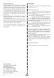
Installation and Operating Guide 38.AS MADE IN GERMANY GB IP x4 1 Druck Nr. 29342172en / - 44.
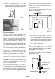
Dear customer: General instructions Please note that optimum sauna climate conditions can be achieved only if the cabin ventilation (fresh air and exhaust) system, the sauna heater and the control unit are designed and set to work efficiently in combination. You have purchased a high-quality sauna heater that will give you years of sauna bathing pleasure.
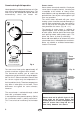
l Caution: Due to the high temperatures generated during operation of the sauna heating unit, direct contact with the unit can cause burns. Special Instructions Improper installation can create fire hazards! Please read the installation guide carefully and completely. Strict attention should be paid to dimensional data and to the following special instructions. l The sauna heating unit is not designed for installation/use in a niche, beneath the reclining bench or beneath an inclined ceiling.
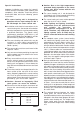
Power input in kW 4,5 6,0 7,5 9,0 12,0 Minimum diameters in mm2 (copper lead) for connection to 380400 V AC 3N Suitable for cabin size in m3 Power line from power grid to control unit ca. 4 - 6 ca. 6 - 10 ca. 8 - 12 ca. 10 - 14 ca.
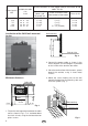
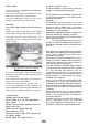
. Secure the sauna heating unit to the wall mounting bracket by inserting a sheet metal screw through the hole positioned at the rear edge of the heater (Fig. 5 and 6). Please remember that the sensor lines are thin, flexible tubes that must not be squeezed or subjected to pressure. These lines must never be cut, as this will destroy the components. 18 cm 20 cm 25 cm Fig. 5 Securing screw Fig.6 Fiig.
Commissioning/Initial operation Sauna stones Heater operation is initiated with the timer unit. You may select a heating period of up to 4 hours. The timer runs for the selected time period and then automatically shuts the heater off. Sauna stones are natural materials. Check your sauna stones at regular intervals, since they are susceptible to the effects of strong steamwater additives and may decompose over a long period of time. Consult your sauna supplier if you have any questions.
Instructions Leakage current Safety cutoff For the installation of sauna heaters, please pay attention to the DIN VDE 0100 part 703 ! The sauna heater is equipped with a temperature limiter for security. In case of a malfunction this temperature limiter cuts off all 3 phases by safety reasons. Once the temperature limiter has cut off the current, he must be reset mechanically. This standard makes the following statement valid in your newest expenditure, since February 2006, paragraph 703.412.
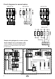
Circuit diagrams for sauna heaters 7500 W 2500 W 2500 W 6000 W 1500 W 1500 W 1500 W 1500 W 6000 W U V W N U V W N 2500 W 400 V AC 3N 400 V AC 3N 2000 W 2000 W 2000 W 400 V AC 3N U V W N Sample wiring diagram for a sauna system Circuit diagram for 7.5 kW heaters (with 7 kW 3 heating coil units of 2000 W each) Important! The ground lead (N) must always be connected. N L1 L2 L3 Sauna lamp Fuses U V W N 4-hr.
Care and maintenance All sauna heating units are made of corrosion-resistant material. However, to ensure that you get maximum enjoyment from your sauna system for as long as possible, the unit should be cleaned and maintained on a regular basis. All openings and baffle plates must be free of obstruction at all times. These areas are susceptible to deposits of dust and fluff drawn into the unit with fresh air. This impairs the air-convection process in the sauna heating unit and can lead to overheating.