
Technical data

6
GB
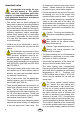
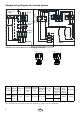
Sample wiring diagram for a sauna system
N L1 L2 L3
S a u n a
lamp
Fuses
M a i n
p o w e r
switch
Distribu-
tor box
4-hr. opera-
ting timer
Temperature limiter
Thermostat
Heater
U V W N PE
2500W
2500W
2500W
400 V AC 3N 400 V AC 3N
PEU V W N
1500W
1500W
1500W
1500W
1500W
7,5 kW7,5 kW
U V W N PE
2000W
2000W
2000W
400 V AC 3N 400 V AC 3N
PEU V W N
1500W
1500W
1500W
1500W
6 kW6 kW
Important! The ground lead (N) must always be connected.
Capacity
acc. DIN
Electrical.
Connection
Fuse heater
in A
Connecting
cable main
- heater in
mm²
Temperature
regulation
range
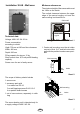
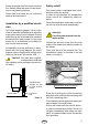
Installation
dimensions
H/W/D cm
For cabin
size
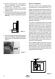
Minimum
dimensions
of air intake
and exhaust
vents
Weight
without
stones
without
package
Stone fi lling
6,0 kW
3N AC
50 Hz
400 V
3 x 16 5 x 2,5 40 - 110° C 78* / 42 / 36
6 - 8 m³ 35 x 4 cm **
15,0 kg 15,0 kg
7,5 kW 7 - 10 m³ 35 x 5 cm **
All cross sections of a line are minimum diameters in mm² (Copper line)
* or in accordance with the instructions of the cabin manufacturer **) during 18 cm ground clearance