
Technical data

8
GB
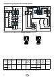
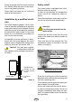
2. Attach connecting line in accordance
with circuit diagram. A circuit diagram is
located in the terminal box.
3. Seal terminal box with cover, spacer
facing outwards. For this use 2 ea. self-
tapping screws
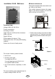
4. Hook the sauna heating unit into the wall
mounting using the mounting slots on the
rear wall and place against the spacer
(Illust. 3).
Abb. 5
5. Das Saunaheizgerät mittels Blechschraube
durch die am hinteren Ofenrand befi ndliche
Bohrung an der Wandhalterung sichern
(Abb.5).
18 cm
Illust. 4
Illust. 5
Mounting screw
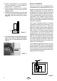
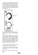
Sensor installation
The built-in control unit is equipped with a
thermostat and an a temperature limiter. The
capillary tube sensors are delivered with the
heater unit (packed in the lower section of
the heater). The sensor must be removed
carefully from the heater and fi xed in position
in the mounting holes on the sensor moun-
ting bracket. The capillary tubes must not
be bent or damaged. The smallest bending
radius should not be less than 4-5 cm during
and after installation.
The sensor mounting bracket is mounted
(using the provided wood screws) to the
cabin wall as shown in Fig. 7, centered
above the heater exhaust outlet facing the
cabin door and positioned 25 cm below the
cabin ceiling, The bracket must be placed
in this position, as otherwise the desired
temperatures cannot be achieved. The
capillary tubes can be fastened to the cabin
wall with the fastening elements provided.
The excess length of capillary tube should
be rolled up behind the heater and must
not be pushed back into the connection box
under any circumstances.
If the installed capillary tubes do not have
an insulating mantle, they must be protected
against contact. This can be accomplished
by running the tubes through the grooves
in the wall paneling and covering them with
appropriate wood molding.
20 cm
25 cm
Illust. 6