Installation and user guide EMOTEC B6000 GB IP x4 Druck Nr. 29342340en GB 43.
Table of Contents General information concerning sauna bathing ..................................................... 3 Scope of delivery .................................................................................................. 4 General safety precautions ................................................................................... 4 Assembly of the control unit ................................................................................. 4 Wall mounting ..................................
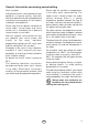
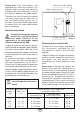
General information concerning sauna bathing Dear customer, Please note the variation in temperatures in the cabin while sauna bathing. The hottest area is directly under the cabin ceiling, whereas there is a steady temperature gradient towards the floor of the cabin. Inversely, the relative humidity is lowest directly under the cabin ceiling and the highest on the cabin floor.
Package contents assembly instructions, especially when installing the temperature sensor. The temperature above the oven is critical for the temperature setting. The temperature can be held within operating parameters and a minimal temperature gradient inside the bench area of the sauna cabin can be achieved only if unit is assembled correctly. (subject to change) Included with the control unit are: 1.
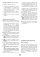
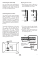
3 3 Illust . 3.2 Illust. 1 Illust . 3.3 3. Hang the control unit onto the 3 mm projecting screw. Insert the included rubber sleeves into the openings on the back side of the housing and lead the electrical cable through these openings. Screw the lower part of the housing onto the cabin wall using the lower threaded holes. (Illust. 4) 1. Remove the cover of the control unit. To do this press the fastening tab inwards with a flat screwdriver and remove the housing top by pivoting it upwards (Illust.1).
Lead wire for cabin lighting Please note: If the sauna cabin is not equipped with electrical conduits, the electrical cables must be lead along the outside of the cabin, preferably in one of the recesses between the wood boards. Therefore, you have to mount the control unit farther away from the cabin wall, so you can lead the cables into the unit. In this case, use the included 3 spacer tubes as shown in Illust. 3.3, which hold the lower part at a distance.
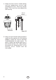
Mounting the oven sensor Connecting the sauna lamp 1. Mount the oven sensor in cabins up to 2 x 2m according to Illust. 6 and 7, in larger cabins according to Illust. 6 and 8. The sauna lamp must be splashproof (by Standard IPx4) and resistant to ambient temperature. The sauna lamp can be mounted anywhere except in the area of the rising hot air above the oven. Connecting the sensor lines 35 cm 19 cm You should not install sensor and power supply lines together, or lead them through the same conduit.
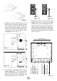
4. Attach the lines for the shutoff (white) and the temperature sensor (red) according to Illust. 10 to the sensor board. Then insert the sensor board into the housing. red red white (Limiter) Housing white (Limiter) Sensor Ô Sensor board Illust. 10 5. After you are finished installing and have made sure the control unit is functioning properly, check the line for overheat shutoff protection for short circuits. To do this, release one of the white lines in the sensor housing.
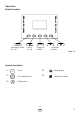
Operation Button Functions Mode Operating switch on - off Lamp on - off Program button Selection buttons Illust.
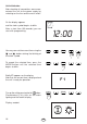
Unit initialization After checking all connections once more, connect the unit to the power supply by switching on the fuse and the main switch. On the display appears and the clock symbol begins to blink. After a short time (30 seconds) you can start with programming. 12:00 You may now set the current time using the and buttons during the blinking of the clock symbol. Mode To accept the selected time, press the MODE-button until the selected time begins to blink.
Default parameters Finnish sauna operation 20:03 After switching on the unit, the display alternates between the time of day and the remaining heating time. 05:58 Temperature indicator The temperature is displayed on the righthand side of the display by a thermometer symbol. preselected temperature An arrow on the right side of the thermometer displays the pre-selected temperature. The colored area of the thermometer displays the current temperature in the cabin.
If you wish to end your sauna bath prematurely, press the button. Mode The symbol on the display then disappears. Important notes when programming Every modification of the preset parameters must be confirmed by pressing the "MODE" button. If you do not press the "MODE" button, the unit will automatically default back to the previous parameters.
Changing the default temperature Temperature setting By default the temperature for Finnish operation is set to 95°C. To change this parameter, press the "MODE" button. P1 P1 then appears on the display in the programming area. P3 button repeatedly until P3 Press the and the heating symbol appear on the display, and confirm this with the "MODE" button. 90 The thermometer symbol appears, and the heating symbol begins to blink. Use the selection buttons and to set the temperature.
Using the selection buttons and you can now set heating time. Please consider, though, that the cabin needs 40-50 minutes for warming up, to create a pleasant climate in the cabin. For example, if you wish to take your sauna bath at 6 p.m., then you should set the startup time to 5:10 p.m. 17:10 Confirm the selected time by holding the "MODE" button. P1 briefly appears on the display. As long as P1 is shown on the display, P1 button to start the delayed press the start-up sequence.
Programming current time To reach this program level, press the "MODE" button and the button simultaneously until F1 is displayed, as well as the clock symbol. F1 You can change the time with function F1. Confirm with the "MODE" button and the previously set time begins to blink with the clock symbol. 20:03 and Set the current time using the buttons (e.g. when adjusting daylightsavings time). Confirm your selection by pressing and holding the "MODE" button, until the entered value begins to blink.
The control unit switch The control unit switch can be found on the top end of the unit. Using this switch, you can isolate the electronics from the mains supply in case of a breakdown. Please note that operating the control unit switch returns all settings to the factory settings. Control unit switch = unit switched on In case of breakdown, press the control unit switch on the left part of the rocker to the first position (switch position 0). The unit is now completely switched off.
Technical data Rated voltage: 400 V 3 N 50 Hz AC Schaltleistung: max 9 kW resistive load (AC 1 operation) upgrade to 36 kW possible through connection to power control units Heating time shut-off: 6h Display: Protection type: LCD, backlit IPx4 in accordance with DIN 40050 (German Standards Institution), splashproofing Control range, sauna operation: 30 to 115°C Sensor system: KTY-Sensor with overheat shutoff protection at 139° C Control characteristics: digital two-step control of -20° C - max.
GB W W P max 9.
$ Service address: EOS-Werke Günther GmbH D-35759 Driedorf, Germany Tel. +49 (0) 27 75 8 22 40 Fax +49 (0) 27 75 8 24 55 e-mail: servicecenter@eos-werke.de Internet: www.eos-werke.de Guarantee - The period of warrenty starts from the date of purchase and lasts up to 2years for commercial use and 3 years for private use. Please keep this address together with the installation guide in a safe place.