CQB-TM-ITI OPERATOR MANUAL FOR THE Clip-On Night Vision Device - Thermal (CNVD-T) Rev.
SAFETY SUMMARY 1. GENERAL SAFETY INSTRUCTIONS This manual contains operating instructions and maintenance procedures which may cause injury or death to personnel, or damage to equipment if not properly followed. Prior to performing any task, the WARNINGs, CAUTIONs and NOTEs included in that task shall be reviewed and understood. 2. WARNINGS, CAUTIONS AND NOTES Safety headings used in this manual and their respective definitions are as follows: WARNING..
3. SAFETY PRECAUTIONS The following general safety precautions supplement the specific WARNINGs, CAUTIONs and NOTEs that appear elsewhere in this manual. 3.1 Batteries. The Clip-On Night Vision Device – Thermal (CNVD-T) is powered by four lithium DL123A batteries. The following safety precautions apply when handling lithium batteries: • Do not short circuit, puncture, incinerate, or disassemble. • Do not attempt to recharge. • Prior to use, inspect all batteries for cracks, dents, leakage, or bulging.
WARNING.. Use of incorrect batteries poses a risk of fire or explosion. Be aware that batteries do exist with similar physical characteristics to the DL123A battery, but with a different voltage and/or polarity path. Ensure that only 3V lithium batteries with a raised positive (+) terminal are installed in the CNVD-T. WARNING.. Use of off-brand batteries poses a risk of fire or explosion.
WARNING.. Remove the CNVD-T from the weapon before inspecting, cleaning, or performing other maintenance functions. 3.3 Operation and Maintenance. CAUTION.. Use of acetone or gun cleaning agents containing perchloroethylene or methylene chloride may permanently damage the CNVD-T system. CAUTION.. Pointing the CNVD-T directly at the sun without the lens cover installed (and closed) may permanently damage the thermal assembly.
TABLE OF CONTENTS SAFETY SUMMARY ....................................................................... i TABLE OF CONTENTS ................................................................. v LIST OF FIGURES ....................................................................... vii LIST OF TABLES ......................................................................... vii CHAPTER 1 ......................................................................................1-1 INTRODUCTION .....................
TABLE OF CONTENTS (cont'd) 2.14 EXTERNAL MONITOR .....................................2-20 SECTION III ..........................................................................2-22 ZEROING PROCEDURES .............................................2-22 2.15 ZEROING ON A 25-METER RANGE ...............2-22 CHAPTER 3 ......................................................................................3-1 MAINTENANCE AND SERVICING ............................................3-1 SECTION I ........................
LIST OF FIGURES Figure 1-1 Clip-On Night Vision Device – Thermal (CNVD-T) ........ 1-1 Figure 1-2 CNVD-T Major Components ..........................................1-5 Figure 2-1 Battery Installation ..........................................................2-2 Figure 2-2 Throw-Lever Mount ........................................................2-3 Figure 2-3 CNVD-T Mounted with ACOG® .....................................2-5 Figure 2-4 CNVD-T Controls and Adjustments ...............................
viii
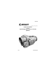
CHAPTER 1 INTRODUCTION SECTION I GENERAL INFORMATION Figure 1-1 Clip-On Night Vision Device – Thermal (CNVD-T) 1.1 SCOPE This manual is intended for use by operators of the Clip-On Night Vision Device - Thermal (CNVD-T). It provides a system description, operational procedures, and maintenance responsibilities. Complete familiarization with this manual prior to using the equipment will ensure safe operation and maximum effectiveness of the CNVD-T. 1.
1.3 MANUFACTURER L-3 Insight Technology Incorporated 9 Akira Way Londonderry, NH 03053 USA 1.4 PURPOSE OF EQUIPMENT The CNVD-T is a handheld or weapon-mounted thermal imaging device that allows for observation, target identification, and passive target acquisition during the day or in adverse conditions such as light rain, light snow, dry smoke, and low light to total darkness. 1.5. ABBREVIATIONS AND ACRONYMS Abbreviations and acronyms used in this manual are spelled out the first time they appear.
SECTION II EQUIPMENT DESCRIPTION 1.6 SYSTEM DESCRIPTION The CNVD-T is a battery operated, handheld or weaponmounted, thermal imaging device. It allows for observation, target identification, and target acquisition during the day or in adverse conditions such as light rain, light snow, dry smoke, and low light to total darkness. The unit will not allow the user to see through glass, water, or heavy rain / snow.
1.7 TECHNICAL SPECIFICATIONS Table 1-1 Technical Specifications WEIGHT AND DIMENSIONS Weight (with batteries) Length Width Height < 22.4 ounces (635 grams) 6.0 inches (15.2 cm) 2.7 inches (6.9 cm) 3.3 inches (8.4 cm) POWER Batteries 4 DL123A lithium batteries * Battery Life 7.
1.8 LIST OF MAJOR COMPONENTS The CNVD-T system includes the components shown in Figure 1-2. Table 1-2 provides a brief functional description of each item. The “Key” column in Table 1-2 corresponds to the label numbers in Figure 1-2.
Key Major Component Function 2 Soft Carrying Case Protects the CNVD-T and accessories while in a field environment. 3 Operator Manual Provides detailed operating and maintenance instructions specific to the CNVD-T. 4 Quick Reference Guide Provides at-a-glance operating procedures for the CNVD-T. 5 Lens Cleaning Kit A lens brush, lens tissue, and anti-fog solution used to clean the optical lenses of the CNVD-T. 6 Batteries, DL123A Four 3V DL123A lithium batteries used to power the CNVD-T.
CHAPTER 2 OPERATING INSTRUCTIONS SECTION I PREPARATION FOR USE AND INSTALLATION 2.1 PREPARATION FOR USE 2.1.1 Unpacking the Equipment. Before unpacking the equipment, verify that all major components listed in Table 1-2 are present. Check the CNVD-T assembly to ensure the following additional items are included: a. Battery Door b. Objective Lens Cover c. Video Jack Plug If any of the major components or items listed above are missing, seek guidance from the equipment issuing authority. 2.1.
2.2.2 Battery Installation. Open the battery compartment by turning the thumbscrew located in the center of the battery door counterclockwise. Install four DL123A lithium batteries with the positive ends facing up as shown in Figure 2-1. Reseat the battery door on the battery compartment and tighten the thumbscrew by turning clockwise until snug. Figure 2-1 Battery Installation CAUTION.. Do not ship or store the CNVD-T with batteries installed.
2.2.3 Low Battery Power. A low battery message will appear in the eyepiece display when approximately 20 minutes of continuous operation remain. If the batteries are not replaced promptly when the “LOW POWER” message appears, the display quality will deteriorate rapidly. 2.3 MOUNTING INSTRUCTIONS The CNVD-T is equipped with a throw-lever mounting bracket that is designed for direct attachment to weapons with a MIL-STD-1913 rail.
NOTE The CNVD-T may be placed at any position (forward and aft) on the rail that is most convenient for the operator. If, however, the CNVD-T is removed from the rail, the operator should note the position at which it was zeroed, and return it to that same position to ensure that zero is retained. a. Pull the lever lock out to the full open position. b. Swing the throw-lever toward the front (objective lens) of the CNVD-T to allow the mounting bracket sufficient space to fit over the MIL-STD-1913 rail. c.
2.3.2 Mounting with Other Optics. When mounting the CNVD-T in-line with a day optic, first stretch the interface hood over the eyepiece of the CNVD-T. Mount the day optic to the rail in accordance with manufacturer’s instructions. Mount the CNVD-T to the weapon rail (in front of the optical sight) per paragraph 2.3.1. Ensure the interface hood covers the objective lens of the optic (see Figure 2-3). Figure 2-3 CNVD-T Mounted with ACOG® 2.4 OBJECTIVE LENS AND EYEPIECE 2.4.1 Objective Lens.
2.4.2 Eyepiece. The eyepiece assembly may be fitted with one or both of the following components: 2.4.2.1 When installed, the night vision spectrum filter prevents fogging of the eyepiece, and reduces backlighting and loss of night vision in low light environments. The filter / shield is installed as follows: a. Place the filter / shield over the eyepiece with the threaded side down. b. Carefully turn the filter / shield clockwise to screw it into the eyepiece assembly. c. Tighten until snug. 2.4.2.
SECTION II OPERATING PROCEDURES 2.5 CONTROLS AND ADJUSTMENTS Figure 2-4 shows the features and controls for the CNVD-T. This section provides details regarding their function and operation.
2.6 POWER Pressing the POWER button will turn the unit on. The CNVD-T will power up with the same settings selected as when the system was last turned off. With the system powered on, the CNVD-T can be placed in a Standby Mode by pressing and holding the MENU / ZOOM button for about 3 seconds. Pressing any of the LEFT / RIGHT / UP / DOWN buttons will reactivate the unit. Upon “waking” from Standby Mode, the unit will retain all settings entered by the operator prior to being placed in standby.
2.7.1.1 Pressing the MENU / ZOOM button calls up the Main Menu (see section 2.12). 2.7.1.2 Pressing the MENU / ZOOM button twice in rapid succession (double-tapping) toggles between a 1x and 2x magnified viewed image (see section 2.12.1). 2.7.2 UP / DOWN Buttons. The UP / DOWN buttons are used to control the brightness of the display. They are also used to scroll through menu items when the Main Menu is displayed. 2.7.3 LEFT / RIGHT Buttons.
Brightness of the display is adjusted by pressing the UP / DOWN buttons to move the status bar along the MIN / MAX scale. Repeatedly pressing the UP / DOWN buttons will move the status bar in single increments. Pressing and holding the UP / DOWN buttons will auto-scroll the status bar in multiple increments. If the UP / DOWN buttons are not pressed within 3 seconds, the brightness scale will disappear and the CNVD-T will revert to normal viewing mode.
If the LEFT / RIGHT buttons are not pressed within 3 seconds, the contrast scale will disappear and the CNVD-T will revert to normal viewing mode. Once adjusted, the contrast will remain at the applied setting (even if the CNVDT is turned off) until readjusted by the operator. 2.9.1 Auto-Gain Control. The CNVD-T may also be placed in one of two auto-gain modes: a. AUTO-LOW mode is accessed by repeatedly pressing the RIGHT button to move the status bar along the contrast scale.
2.11 STARTUP PROCEDURES To achieve optimal performance and image clarity, the following procedures should be accomplished in the order presented, each time the CNVD-T is to be placed into operation: a. Install batteries per paragraph 2.2.2. b. Turn on the CNVD-T by pressing the POWER button. Wait 2 to 5 seconds until the system begins imaging. c. Install the objective lens cover and perform a calibration as described in paragraph 2.12.3. d.
Menu items are then selected (underlined) by scrolling with the UP / DOWN buttons. Where available, sub-menus are accessed by pressing the LEFT / RIGHT buttons. Activation of the selected menu item is accomplished by again pressing the MENU / ZOOM button. If there is no button activity within approximately 10 seconds, the Main Menu will disappear and the CNVD-T will revert to normal viewing mode.
2.12.2 Polarity (POL). Activating the POL menu item allows the operator to toggle between white hot (WH) and black hot (BH) polarity modes and is accomplished as follows: ZOOM 1X POL CAL RETINT RET RS170 EXIT Figure 2-9 Menu – Polarity (POL) which calls up this sub-menu: WH BH Use the LEFT / RIGHT buttons to select the desired polarity mode and press the MENU / ZOOM mode to activate.
Activating the CAL menu item initiates a calibration of the CNVD-T. After prolonged use, or after transitions from one temperature extreme to another, a degradation of the thermal image may be noticed. When this occurs, the CNVD-T should be calibrated as follows: a. Install the objective lens cover over the objective lens to block out all available light. b. Activate the CAL menu item as shown below. c. The message “CALIBRATING” will appear as the unit performs the calibration.
2.12.4 Reticle Intensity (RETINT). Activating the RETINT menu item allows the operator to adjust the color of the reticle from white, through the gray scale to black, to provide the best contrast with the viewed image. ZOOM 1X POL CAL RETINT RET RS170 EXIT Figure 2-11 Menu – Reticle Intensity (RETINT) During adjustment, a color scale is presented in the eyepiece display as shown in Figure 2-12.
be placed in an auto-intensity mode by repeatedly pressing the UP button until the status bar is at the extreme upper (WHITE) end of scale and the word AUTO appears. 2.12.5 Reticle (RET). Activating the RET menu item allows for repositioning the reticle and toggling it on or off. ZOOM 1X POL CAL RETINT RET RS170 EXIT Figure 2-13 Menu – Reticle (RET) Control Once selected, the following sub-menu will appear in the eyepiece display: EXIT POS OFF 2.12.5.
b. When in ZOOM 1X mode, the reticle is moved in 2-pixel increments each time the UP / DOWN / LEFT / RIGHT buttons are pressed. The reticle is moved in 1-pixel increments when in ZOOM 2X mode. See section 2.15 for click equivalents and zeroing information. POS ADJ AZ 8 L EL 2 U Figure 2-14 Reticle Position Adjustment 2.12.5.2 Activating the OFF sub-menu item turns the reticle off. Turning the reticle back on is accomplished by selecting the RET menu item from the Main Menu. 2.12.6 RS170 / VGA.
NOTE When viewing the CNVD-T thermal image on an external monitor, the RS170 video format must be selected. Using the VGA video format for this purpose will result in an extremely distorted image. 2.12.7 Exit (EXIT). Exiting the Main Menu is accomplished by either activating the EXIT menu item or pressing the LEFT or RIGHT button. Exiting the Main Menu saves all changes made and returns the CNVD-T to normal viewing mode.
2.13 SHUTDOWN PROCEDURES a. Press and hold the POWER button for approximately 3 seconds as the messages OFF? then OFF! appear sequentially in the eyepiece display. Release the POWER button when the eyepiece display turns dark. b. Install the objective lens cover over the objective lens. c. Remove all batteries; place batteries and the CNVD-T in the soft carrying case. 2.
Viewing live imagery from the CNVD-T on an external monitor is accomplished as follows: a. Remove the video jack plug (captive to the CNVDT2) from the video jack. b. Plug the CNVD-T connector into the video jack. c. Attach the BNC connector to an external monitor or television. d. Follow the CNVD-T startup procedures contained in section 2.11 and ensure RS170 video format is selected from the Main Menu as described in paragraph 2.12.6. e.
SECTION III ALIGNMENT / ZEROING 2.15 ZEROING ON A 25-METER RANGE 2.15.1 Clip-On. WARNING.. Activating ZOOM 2X when the CNVD-T is used inline with other optical sights may induce an error in the aiming function of those devices. When being used in-line with an optical sight, the CNVD-T should be placed in ZOOM 1X, the reticle should be turned off, and zeroing procedures associated with the primary sight should be used.
When being used as a stand-alone device, the example below shows how to align the CNVD-T2 to be parallel with the rail of the host weapon on a 25-meter range. This “infinite parallel” configuration is appropriate for many mission profiles. Once parallel, the CNVD-T2 / weapon combination may be zeroed in accordance with established unit, departmental, or agency procedures. a. Once mounted to a weapon, the distance from the top of the rail to the centerline of the CNVD-T objective lens is 5.9cm.
b. Mark the designated strike point on a standard 25meter zeroing target. c. Draw a designated strike zone around the strike point that corresponds in size to an acceptable degree of desired accuracy. Figure 2-19 Designated Strike Zone d. Mount the target on an “E” silhouette or other suitable surface at 25 meters. e. Mount the CNVD-T to the weapon.
f. Turn on the CNVD-T using the startup procedures in section 2.11. g. Align the CNVD-T reticle with the center of the target per paragraph 2.12.5. h. Fire a 3-round shot group and note the center of the shot group relative to the designated strike point. i. Adjust the position of the reticle to move the center of the shot group to the designated strike point. j. Fire another 3-round shot group and again observe the center of the new shot group relative to the designated strike point. k.
2-26
CHAPTER 3 MAINTENANCE AND SERVICING SECTION I MAINTENANCE AND TROUBLESHOOTING 3.1 MAINTENANCE PROCEDURES The operator should inspect the CNVD-T before each use and after it has been in extreme conditions, such as prolonged exposure to intense temperatures. The following procedures will prolong the life of the CNVD-T and help ensure safe operation. 3.1.1 Batteries. Inspect the batteries for cracks, dents, leakage, or bulging. If a battery shows signs of damage, remove and dispose of properly.
3.1.4 CNVD-T Housing. Inspect the CNVD-T housing for any signs of damage including cracks, missing parts, and any other visible defects. Rinse the CNVD-T housing with water and wipe clean with a soft cloth. Clean around buttons and attachment points with a cotton swab. 3.1.5 Video Jack. Inspect the video jack for corrosion, dirt and damage. Gently remove any large particles of foreign matter and clean the contacts with a cotton swab and isopropyl alcohol. 3.
(4) Place the unit in auto-gain mode per section 2.9.1. c. No Reticle is visible. (1) Adjust display brightness per section 2.8. (2) Ensure reticle is turned on per paragraph 2.12.5. (3) Adjust reticle intensity per paragraph 2.12.4. d. Poor or degraded image. (1) Perform a calibration per paragraph 2.12.3. (2) Remove night vision spectrum filter, if installed. Clean eyepiece and objective lens. (3) Inspect the night vision spectrum filter for dirt, grime, scratches, and cracks.
CAUTION.. Creating too much tension with the locknut may result in damage to the mounting bracket when the throw-lever is forced against the weapon rail. Creating too little tension with the locknut may allow for movement of the CNVD-T on the rail. Never completely remove the locknut from the mounting bracket. a. Swing the throw-lever closed (against the body of the CNVD-T), then push in the lever lock to engage the locking mechanism. b.
3.3.2 Replacing Objective Lens Cover and Lens Cover Strap. No tools are required to perform this procedure. a. Pull both ends of the existing strap off their respective retaining pins (located on the CNVD-T housing). b. While holding the lens cover in one hand, use the other hand to pull the strap over, and off, the center stud of the lens cover. c. Work the large, center eye of the replacement strap over the center stud of the lens cover, ensuring it lays flat against the surface with the glossy side down.
3.3.3 Replacing Battery Door Lanyard. Vibra-Tite® (or equivalent) and a T-7 Torx wrench are required to perform this procedure. NOTE This procedure is best performed with the battery door installed (closed). NOTE Because the lanyard mounting screw is installed at the factory with a small amount of bonding material, it is normal to encounter resistance when removing it. a. Use a T-7 Torx wrench to remove the lanyard mounting screw. b. If necessary, pull the lanyard over, and off, the battery door thumbscrew.
Figure 3-3 Replacing Battery Door Lanyard f. Apply a small bead of Vibra-Tite® (or equivalent) to the threads of the mounting screw and use a T-7 Torx wrench to install. 3.3.4 Replacing Video Jack Plug Assembly. Vibra-Tite® (or equivalent) and a T-7 Torx wrench are required to perform this procedure. a. Turn the video jack plug counterclockwise until it is unscrewed from the video jack.
b. Use a T-7 Torx wrench to remove the lanyard mounting screw. c. Position the replacement parts so that they can be assembled as shown in Figure 3-4. Figure 3-4 Replacing Video Jack Plug Assembly d. Apply a small bead of Vibra-Tite® (or equivalent) to the threads of the mounting screw and use a T-7 Torx wrench to install.
SECTION II SERVICE / PACKING AND UNPACKING 3.4 RETURN INSTRUCTIONS 3.4.1 For service, repair, or replacement, first e-mail returns.insight@l-3com.com or call toll-free 1-877-744-4803. 3.4.2 To assist with determining if the item is repairable, the following information shall be provided: a. Serial number of the defective item; b. Thorough description of the malfunction, defect, or damage; and c. If known, an explanation as to how the malfunction, defect or damage occurred.
3.4.4 Place the item and a copy of the test report or detailed description of the failure in a suitable packing container. Mark the package with “Field Return” and the RMA number. Ship via fastest, traceable, pre-paid means to L-3 Insight Technology Incorporated, 9 Akira Way, Londonderry, NH 03053. 3.5 WARRANTY INFORMATION The CNVD-T is under warranty from defects in material and workmanship for a minimum of one (1) year from the date of manufacture.
APPENDIX A REPAIR PARTS / ACCESSORIES A.1 Scope This Appendix provides an organizational level parts list for the CNVD-T. Table A-1 lists spares, parts, and assemblies authorized for repair / replacement at the operator level. Special tools or equipment are not required for these repairs.
Table A-1 Repair Parts / Accessories (cont’d) PART NUMBER TBD MS15795-844B 5855-01-561-8141 CQB-635-02 NSN 5855-01-561-8057 CQB-062-02 A-2 DESCRIPTION Washer, Video Jack Plug Video Jack Plug Retaining Strap, Video Jack Plug
The CNVD-T Is designed and produced by: L-3 Insight Technology Incorporated 9 Akira Way Londonderry, NH 03053 USA www.insighttechnology.com This manual contains technical data whose export is governed by the U.S. International Traffic in Arms Regulations (ITAR). This information must not be transferred to a foreign person without the proper authorization of the U.S. Government. Please contact L-3 Insight Technology for more information.