Eobody3 SensorBox User’s Manual USB8/USB8M/USB16/USB16M eowave
Table des matières Word n'a pas trouvé d'entrées pour votre table des matières. Dans le document, sélectionnez les mots à inclure dans la table des matières, puis, dans Palette de mise en forme, sous Styles, cliquez sur un style d'en-tête. Répétez l'opération pour chaque en-tête à inclure, puis insérez la table des matières dans le document. Vous pouvez également créer une table des matières en cliquant sur l'option Créer avec mise en forme manuelle, puis tapez les entrées manuellement.
Safety instructions • • • • • • • • • • Before using your Eobody3, make sure you have read the following instructions carefully. Do not open or modify the unit or its main adapter when the unit is externally powered. During lightning, unplug the unit; make sure the main adapter (if one) is not plugged. Before cleaning your Eobody3, make sure the main adapter and/or any external elements are disconnected from the unit. Do not try to repair the interface or the components inside of it.
Powering When using usb or an external powering, you need to set Eobody3 external switch to the right position. USB powering Eobody3 is USB self-powered. Just plug the usb from Eobody3 to your computer usb in. External powering You will need an external powering in the following cases: • Some sensors need more than the usb 3,3V. In this case, you can power the unit externally with a 9 V DC / 500 mA power supply. Connect the 9 V DC / 500 mA power supply into the power plug connector of Eobody3.
• load to file load configuration from your computer hard drive. Eobody3 internal memory configuration • check current parameters check the internal memory of Eobody3 unit. • save current parameters save current parameters inside the Eobody3 internal memory. Eobody3 has an internal memory to store parameters settings. You may store an entire installation or performance configuration inside one or more Eobody3 and keep it (or them) as back-up units for a future use.
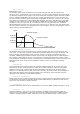
HVVDJH HU • Note on message N-ON trigger hi-low The analogue signal must correspond to an envelope changing with time and which has a XH VLJQDO PXVW FRUUHVSRQG WR DQ HQYHORSH FKDQJLQJ ZLWK WLPH DQG ZKLFK KDV D maximum value. 3 parameters need to be specified: note sent, higher threshold, and lower threshDOXH SDUDPHWHUV QHHG WR EH VSHFL¿HG QRWH VHQW KLJKHU WKUHVKROG ORZHU WKUHVK old.
DQDORJXH LQSXW 7KLV SDUDPHWHU YDOXH PD\ FRUUHVSRQG WR D 0,', QRWH QXPEHU D 0,', FRQWUROOHU QXPEHU RU D 0,', SURJUDP QXPEHU GHSHQGLQJ RQ WKH W\SH RI 0,', PHVVDJH ZKLFK LV FKRVHQ &RQ¿JXUDWLRQ PDS IRU DQDORJXH LQSXWV Configuration map for analogue inputs ;`WL VM TLZZHNL 9LZ =HS\L /P 3V^ ** *VU[YVS *OHUNL IP[Z ** ]HS\L ** *VU[YVS *OHUNL IP[Z ** ]HS\L 5V[L 5V[L VU [YPNNLY IP[Z UV[L U\TILY OPNOLY [OYLZOVSK SV^LY [OYLZOVSK 7* 7YVNYHT *OHUNL IP[Z 7.
Eobody3 sensorbox with 0-5V inputs (USB8/USB8M/USB16/USB16M) (RERG\ 86% 6HQVRU%R[ 7XWRULDOV 7 Inputs are Neutrik TRS double jacks 6’35. TRS format has been chosen because this is a world (RERG\ 86% 6HQVRU%R[ /LYH 6HQVRU &RQWUR wide used format that can be found anywhere and easily repaired. On sensors inputs, TRS jack tips are powered with 5V. 0-5V inputs have a 1 pole low-pass filter and a buffer to accept different signals and filter data before the A/D conversion.
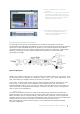
VWHS &KRRVH WKH SDUDPHWHU \RX ZDQW WR PRGXODWH • Choose the parameter you want to :LWK \RXU PRXVH FOLFN RQ WKH SDUDPHWHU \RX ZDQW WR PRGXODWH ZLWK D modulate VHQVRU 7KH VHOHFWHG SDUDPHWHU ZLOO WXUQ SXUSOH $XWRILOWHU IUHTXHQFH LQ • With your mouse, click on the parameter H[DPSOH 6OLJKWO\ PRYH \RXU VHQVRU you want to modulate with a sensor. The selected parameter will turn purple. Auto filter frequency in this example. Slightly move your sensor.
DQDORJXH ]RRP ³DQDORJXH ]RRP´ FRQWUROV WKH LQWHUQDO 3*$ 3URJUDPPDEOH *DLQ $PSOL¿HU JLYHV D IDFWRU RI DPSOL¿FDWLRQ 7KH XVH RI DQDORJXH ]RRPLQJ ZLOO NHHS WKH IXOO ELW GHSWK RI YDOXHV GLJLWDO ]RRP DQG RIIVHW • digital zoom and offset GLJLWDO ]RRP PD[ PLG ORZ RII RQ digital zoom: max/mid/low/off on 7 offset: -127 to +127 RIIVHW WR 40+0 KH[H IP[Z +PNP[HS ]HS\L IP[Z 40+0 JVU]LYZPVU % VHQVRU LQWHUIDFH 3DUDPHWHUV ZLQGRZ aVVT ZL[[PUN $ YLHS ZLUZVY YHUNL
• curve Eobody3 has a new pre-processing tool called curve (for response curve). This wave shaping new feature allows changing the curve of a signal. For example, the linear response of a volume pedal can be changed to a logarithmic or exponential response.
Sensors pre-mapping All Eowave sensors are ready to use with Eobody3 Sensorboxes. They have been designed to get the best signal response with additionnal filters and amplifying circuitry. They are calibrated for maximum bandwidth. Many are plug&play and do not need extra processing. The following table is for Eowave sensors only. More information on each sensor can be found in the sensors datasheet available on www.eowave.
,9 0DNLQJ P\ RZQ VHQVRUV Making my own sensors ,9 0DNLQJ P\ RZQ VHQVRUV ,9 0DNLQJ P\ RZQ VHQVRUV HRERG\ VXSSRUWV PDQ\ NLQG RI VHQVRUV 0RVW FRPPRQ VHQVRUV DUH VZLWFKHV DQG SRWHQWLRPHWHUV Eobody3 supports many kinds of sensors. Most common sensors are switches and potentiometers, EXW WKHUH DUH PDQ\ RWKHU NLQGV RI VHQVRUV but there are many other kinds of sensors.
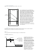
How to connect standard expression pedals or footswitches to my Eobody3 7XWRULDO +RZ WR FRQQHFW VWDQGDUW H[SUHVVLRQ SHGDOV 7XWRULDO +RZ WR FRQQHFW VWDQGDUW H[SUHVVLRQ SHGDOV There are mainly two wiring norms for pedals on the market: the Yamaha norm and the Roland RU IRRWZLWFKHV WR P\ (RERG\ RU IRRWZLWFKHV WR P\ (RERG\ norm. With your Eobody3, you may use directly all expression pedals or footswitches at the Yamaha norm.
Amplification $PSOL¿FDWLRQ Some sensors have a weak signal out and need amplifying. To avoid undesirable noises, the amplifier should be placed as close as possible from the sensor.
FLDOO\ GHYHORSSHG IRU PXVLF DQG YLGHR DSSOLFDWLRQV 3& 0DF ,QWH FRPSDWLEOH (RERG\ (GLWRU HQDEOHV WR DGMXVW LQWHUQDO SURFHVV SDU HWHUV DQG VKDSH WKH RXWFRPLQJ VLJQDO ZDYHIRUP VWDWXV DQDORJXH ]RRP GLJLWDO ]RRP RIIVHW LQYHUVH ODJ SURFHVVRU JDWH QRWH RQ 7KHVH VHWWLQJV FDQ EH VWRUHG LQ 6HQVRUER[ QRQ YRODWLOH PHPRU\ QRZ SRVVLEOH WR VWRUH DQ HQWLUH LQVWDOODWLRQ RU SHUIRUPDQFH VHWXS LQVLGH D 6HQVRUER[ DQG VDYH LW IRU D IXWXUH XVH Eobody3 sensorbox with MIDI output (USB8M/USB16M) • Eobody3 with MIDI output
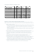
List of MIDI Controllers N° Function Value N° Function Value 0 1 2 3 4 5 Bank Select Modulation wheel Breath control Undefined Foot controller Portamento time 0-127 MSB 0-127 MSB 0-127 MSB 0-127 MSB 0-127 MSB 0-127 MSB 65 66 67 68 69 70 ≤63=off ≥64=on ≤63=off ≥64=on ≤63=off ≥64=on ≤63=off ≥64=on ≤63=off ≥64=on 0-127 LSB 6 7 Data Entry Channel Volume 0-127 MSB 0-127 MSB 71 72 8 Balance 0-127 MSB 73 9 Undefined 0-127 MSB 74 10 11 12 13 14 15 Pan Expression Controller Effect Control Eff
9, 0,', ,PSOHPHQWDWLRQ MIDI implementation -\UJ[PVU¯ ;YHUZTP[[LK 9LJVNUPaLK 9LTHYRZ )HZPJ *OHUULS +LMH\S[ JOHUNLK ? ? 4VKL KLMH\S[ 4LZZHNLZ (S[LYLK 4VKL ? ? ? ? ? 5V[L 5\TILY ;Y\L =VPJL ? ? =LSVJP[` 56;, 65 56;, 6-- ? ? (M[LY ;V\JO 2L` *OHUULS V V ? ? 7P[JO )LUKLY V ? IP[ YLZVS\[PVU *VU[YVS *OHUNL ? TLTVYPZLK 7YVNYHT *OHUNL ? 7YVNYHT U\TILY :`Z[LT ,_JS\ZP]L V V :`Z[LT *VTTVU :VUN 7VZ :VUN :LS ;\UL ? ?
CE norm & FCC INFORMATION 1. Important notice: do not modify this unit! This product, when installed as indicated in the instructions contained in this manual, is compatible with the CE norm & FCC requirements. 2. Important! When connecting this product to accessories and/or another product, use only high quality shielded cables. Cables supplied with this product must be used. Follow all installation instructions.