NTC thermistors for inrush current limiting Leaded and coated disks Series/Type: B57237S0***M0** Date: July 2019 © TDK Electronics AG 2019. Reproduction, publication and dissemination of this publication, enclosures hereto and the information contained therein without TDK Electronics' prior express consent is prohibited.
Inrush current limiters B57237S0***M0** ICLs S237 Applications Inrush current limiting, e.g.
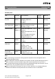
Inrush current limiters B57237S0***M0** ICLs S237 Electrical specification and ordering codes R25 Ω 1 2.2 2.5 4.7 5 7 10 15 22 33 60 Imax (0...25 °C) A 9 7 6.5 5.1 5 4.2 3.7 3 2.8 2.5 2 Ctest1) 230 V AC µF 700 700 700 700 700 700 700 700 700 900 400 Ctest1) 110 V AC µF 2800 2800 2800 2800 2800 2800 2800 2800 2800 3600 1600 Rmin Ordering code (@ Imax, 25 °C) Ω 0.038 0.064 0.074 0.120 0.125 0.172 0.223 0.346 0.383 0.507 0.
Inrush current limiters B57237S0***M0** ICLs S237 Reliability data Test Standard Storage in dry heat IEC 60068-2-2 Storage in damp heat, steady state Thermal schock Endurance Cyclic endurance Maximum permissible capacitance test Test conditions Storage at upper category temperature T: 170 °C t: 1000 h IEC Temperature of air: 40 °C 60068-2-78 Relative humidity of air: 93% Duration: 21 days IEC Lower test temperature: 55 °C 60068-2-14 t: 30 min Upper test temperature: 170 °C t: 30 min Time to ch
Inrush current limiters B57237S0***M0** ICLs S237 Resistance versus temperature S237 series Please read Cautions and warnings and Important notes at the end of this document.
Inrush current limiters B57237S0***M0** ICLs S237 Resistance versus current S237 series Please read Cautions and warnings and Important notes at the end of this document.
Inrush current limiters B57237S0***M0** ICLs S237 Resistance versus current S237 series Please read Cautions and warnings and Important notes at the end of this document.
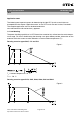
Inrush current limiters B57237S0***M0** ICLs S237 Application notes The following two important aspects for determining the right NTC inrush current limiter are excerpted from the chapter "Application notes" in the "NTC Inrush Current Limiters, Data book". The complete application note can be downloaded from www.tdk-electronics.tdk.com/en/ntcicl_appnotes. 1.4 Load derating The power handling capability of an NTC thermistor cannot be fully utilized over the entire temperature range.
Inrush current limiters B57237S0***M0** ICLs S237 TA = Ambient temperature > 65 °C Tmax = 170 °C The Imax values specified in the data sheets denote the maximum permissible continuous current (DC or RMS values for sine-shaped AC) in the temperature range 0 °C to 65 °C. 1.6 Maximum permissible capacitance The currents during turn-on are much higher than the rated currents during continuous operation.
Inrush current limiters B57237S0***M0** ICLs S237 Figure 4 Maximum permissible capacitance discharging test: typical curves The maximum capacitances that can be switched depend on the individual thermistor type and are given in the data sheets. Please read Cautions and warnings and Important notes at the end of this document.
Inrush current limiters B57237S0***M0** ICLs S237 Taping and packing 1 Taping of radial leaded ICL NTC thermistors according to the specified lead spacing Dimensions and tolerances Lead spacing F = 5.0 mm (taping to IEC 60286-2) for the following types: S153, S235 and S236 Lead spacing F = 7.5 mm (taping based on IEC 60286-2) for the following types: P11, P13, S237, S238 and S364 Please read Cautions and warnings and Important notes at the end of this document.
Inrush current limiters B57237S0***M0** ICLs S237 Dimensions (mm) Lead spacing 5 mm Tolerance of lead spacing 5 mm Lead spacing 7.5 mm Tolerance of lead spacing 7.5 mm ≥12.0 Remarks w ≤12.0 th 6.0 max. 7 max. please refer to dimensional drawings d 0.5/0.6 ±0.05 0.8/1.0 ±0.05 please refer to dimensional drawings P0 12.7 ±0.3 12.7 ±0.3 ±1 mm / 20 sprocket holes P1 3.85 ±0.7 8.95 ±0.8 F 5.0 +0.6/ 0.1 7.5 ±0.8 ∆h 0 ±2.0 0 ∆p 0 ±1.3 0 ±2.0 W 18.0 ±0.5 18.0 ±0.
Inrush current limiters B57237S0***M0** ICLs S237 Types of packing Reel packing Reel dimensions (in mm) Reel type Series pcs. per reel d f n w I S153, S235 1500 360 max. 31 ±1 approx. 45 54 max. I S236 1000 360 max. 31 ±1 approx. 45 54 max. II P11, P13 1500 500 max. 23 ±1 approx. 59 72 max. II S237, S238, S364 1000 500 max. 23 ±1 approx. 59 72 max. Ammo packing Ammo Series type pcs.
Inrush current limiters B57237S0***M0** ICLs S237 Mounting instructions 1 Soldering 1.1 Leaded NTC thermistors Leaded thermistors comply with the solderability requirements specified by CECC. When soldering, care must be taken that the NTC thermistors are not damaged by excessive heat. The following maximum temperatures, maximum time spans and minimum distances have to be observed: Dip soldering Iron soldering Bath temperature max. 260 °C max. 360 °C Soldering time max. 4 s max.
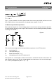
Inrush current limiters B57237S0***M0** ICLs 1.1.2 S237 Wave soldering Temperature characteristic at component terminal with dual wave soldering 2 Robustness of terminations The leads meet the requirements of IEC 60068-2-21. They may not be bent closer than 4 mm from the solder joint on the thermistor body or from the point at which they leave the feedthroughs. During bending, any mechanical stress at the outlet of the leads must be removed. The bending radius should be at least 0.75 mm.
Inrush current limiters B57237S0***M0** ICLs S237 When subjecting leads to mechanical stress, the following should be observed: Tensile stress on leads During mounting and operation tensile forces on the leads are to be avoided. Bending of leads Bending of the leads directly on the thermistor body is not permissible. A lead may be bent at a minimum distance of twice the wire's diameter +2 mm from the solder joint on the thermistor body.
Inrush current limiters B57237S0***M0** ICLs S237 Cautions and warnings General See "Important notes" on page 2. Storage Store thermistors only in original packaging. Do not open the package before storage. Storage conditions in original packaging: storage temperature 25 °C ... +45 °C, relative humidity ≤75% annual mean, maximum 95%, dew precipitation is inadmissible. Avoid contamination of thermistors surface during storage, handling and processing.
Inrush current limiters B57237S0***M0** ICLs S237 Mounting When NTC inrush current limiters are encapsulated with sealing material or overmolded with plastic material, the precautions given in chapter “Mounting instructions”, “Sealing and potting” must be observed. Electrode must not be scratched before/during/after the mounting process. Contacts and housings used for assembly with thermistor have to be clean before mounting.
Inrush current limiters B57237S0***M0** ICLs S237 Symbols and terms Symbol English B B value Ctest Cth Test capacitance Heat capacitance I Imax INTC Itest Current Maximum current within stated temperature range NTC current High test current for additional endurance tests Pmax Maximum power within stated temperature range Rmin RR ∆RR/RR RS RT Minimum resistance Rated resistance Resistance tolerance Series resistance Resistance at temperature T (e.g.
Important notes The following applies to all products named in this publication: 1. Some parts of this publication contain statements about the suitability of our products for certain areas of application. These statements are based on our knowledge of typical requirements that are often placed on our products in the areas of application concerned.
Important notes 7. Our manufacturing sites serving the automotive business apply the IATF 16949 standard. The IATF certifications confirm our compliance with requirements regarding the quality management system in the automotive industry. Referring to customer requirements and customer specific requirements (“CSR”) TDK always has and will continue to have the policy of respecting individual agreements.