Ferrites and accessories RM 8, RM 8 LP Core and accessories Series/Type: B65811, B65812 Date: February 2016 a~í~=pÜÉÉí ¤ EPCOS AG 2016. Reproduction, publication and dissemination of this publication, enclosures hereto and the information contained therein without EPCOS’ prior express consent is prohibited. EPCOS AG is a TDK Group Company.
RM 8 Core and accessories Individual parts Part no.
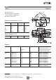
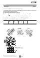
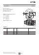
RM 8 Core B65811 ■ To IEC 62317-4 ■ Cores without center hole for transformer applications ■ Delivery mode: sets Magnetic characteristics (per set) 6 l/A le Ae Amin Ve with center hole without center hole 0.68 35.1 52 — 1825 0.59 38 64 55 2430 mm–1 mm mm2 mm2 mm3 12 g Approx. weight (per set) m 10.
RM 8 Core B65811 Ungapped Material AL value nH Pe PV Ordering code -D with center hole -J without center hole W/set N48 2900 +30/–20% 1550 B65811D0000R048 N30 5700 +30/–20% 2690 B65811J0000R030 T38 12500 +40/–30% 5910 B65811J0000Y038 N49 2200 +30/–20% 1040 < 0.37 ( 50 mT, 500 kHz, 100 qC) B65811J0000R049 N87 3300 +30/–20% 1560 < 1.20 (200 mT, 100 kHz, 100 qC) B65811J0000R087 N97 3300 +30/–20% 1560 < 1.
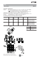
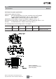
RM 8 Accessories B65812 Coil former, squared pins Material: GFR thermosetting plastic (UL 94 V-0, insulation class to IEC 60085: H max. operating temperature 155 qC), color code black Sumikon PM 9630 ® >E41429 (M)@, SUMITOMO BAKELITE CO LTD Solderability: to IEC 60068-2-20, test Ta, method 1 (aging 3): 235 qC, 2 s Resistance to soldering heat: to IEC 60068-2-20, test Tb, method 1B: 350 qC, 3.5 s Winding: see Data Book 2013, chapter “Processing notes, 2.
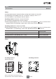
RM 8 Accessories B65812 Coil former for SMPS transformers with line isolation The creepage distances and clearances are designed such that the coil former is suitable for use in SMPS transformers with line isolation. ■ Closed center flange with external wire guide ■ Optimized for use with automatic winding machines Material: GFR thermosetting plastic (UL 94 V-0, insulation class to IEC 60085: F max.
RM 8 Accessories B65812 Coil former for power applications Optimized for automatic winding Material: GFR polyterephthalate (UL 94 V-0, insulation class to IEC 60085: F max. operating temperature 155 qC), color code black Valox 420-SE0 ® >E45329 (M)@, Sabic Innovative Plastic Solderability: to IEC 60068-2-20, test Ta, method 1 (aging 3): 235 qC, 2 s Resistance to soldering heat: to IEC 60068-2-20, test Tb, method 1B: 350 qC, 3.5 s Winding: see Data Book 2013, chapter “Processing notes, 2.
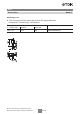
RM 8 Accessories B65812 Clamp ■ With ground terminal, made of stainless spring steel (tinned), 0.4 mm thick ■ Solderability to IEC 60068-2-20, test Ta, method 1 (aging 3): 235 qC, 2 s ■ Also available as strip clamp on reels on request Insulating washer 1 between core and coil former ■ For tolerance compensation and for insulation ■ Made of polycarbonate (UL 94 V-0, insulation class to IEC 60085: E 120 qC), 0.
RM 8 Accessories B65812 Adjusting screw ■ Tube core with thread and core brake made of GFR polyterephthalate Pocan B3235 ® >E245249 (M)@, LANXESS AG Tube core u length (mm) Material Color code Ordering code 3.85 u 5.0 N22 gray Please read Cautions and warnings and Important notes at the end of this document.
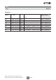
RM 8 »Low Profile« Accessories ■ ■ ■ ■ B65811P To IEC 62317-4 For compact transformers Without center hole Delivery mode: sets Magnetic characteristics (per set) 6l/A le Ae Amin Ve = 0.44 mm–1 = 28.7 mm = 64.9 mm2 = 55.4 mm2 = 1860 mm3 Approx. weight 9.2 g/set Ungapped AL value nH Pe N49 2900 +30/–20% 1020 < 0.33 ( 50 mT, 500 kHz, 100 qC) B65811P0000R049 N92 3100 +30/–20% 1090 < 1.10 (200 mT, 100 kHz, 100 qC) B65811P0000R092 N87 4100 +30/–20% 1440 < 0.
RM 8 »Low Profile« Core B65812 Clamp ■ With ground terminal, made of stainless spring steel (tinned), 0.4 mm thick ■ Solderability to IEC 60068-2-20, test Ta, method 1 (aging 3): 235 qC, 2 s ■ Also available as strip clamp on reels on request Insulating washer 1 between core and coil former ■ For tolerance compensation and for insulation ■ Made of polycarbonate (UL 94 V-0, insulation class to IEC 60085: E 120 qC), 0.
Ferrites and accessories Cautions and warnings Cautions and warnings Mechanical stress and mounting Ferrite cores have to meet mechanical requirements during assembling and for a growing number of applications. Since ferrites are ceramic materials one has to be aware of the special behavior under mechanical load. As valid for any ceramic material, ferrite cores are brittle and sensitive to any shock, fast changing or tensile load.
Ferrites and accessories Symbols and terms Symbols and terms Symbol Meaning Unit A Ae AL AL1 Amin AN AR B 'B B̂ 'B̂ BDC BR BS C0 CDF DF d Ea f fcutoff fmax fmin fr fCu g H Ĥ HDC Hc h h/Pi 2 I IDC Î Cross section of coil Effective magnetic cross section Inductance factor; AL = L/N2 Minimum inductance at defined high saturation ( Pa) Minimum core cross section Winding cross section Resistance factor; AR = RCu /N2 RMS value of magnetic flux density Flux dens
Ferrites and accessories Symbols and terms Symbol Meaning Unit 'L/L L0 LH Lp Lrev Ls le lN N PCu Ptrans PV PF Q R RCu Rh 'Rh Ri Rp Rs Rth RV s T 'T TC t tv tan G tan GL tan Gr tan Ge tan Gh tan G/Pi U Û Ve Z Zn Relative inductance change Inductance of coil without core Main inductance Parallel inductance Reversible inductance Series inductance Effective magnetic path length Average length of turn Number of turns Copper (winding) losses Transferrable powe
Ferrites and accessories Symbols and terms Symbol Meaning Unit D DF De Hr ) K KB Ki Os P P0 Pa Papp Pe Pi Pp' Pp" Pr Prev Ps' Ps" Ptot Temperature coefficient (TK) Relative temperature coefficient of material Temperature coefficient of effective permeability Relative permittivity Magnetic flux Efficiency of a transformer Hysteresis material constant Hysteresis core constant Magnetostriction at saturation magnetization Relative complex permeability Magnetic field constant
Important notes The following applies to all products named in this publication: 1. Some parts of this publication contain statements about the suitability of our products for certain areas of application. These statements are based on our knowledge of typical requirements that are often placed on our products in the areas of application concerned.