Film Capacitors EMI Suppression Capacitors (MKP) Series/Type: B81123 Date: April 2015 © EPCOS AG 2015. Reproduction, publication and dissemination of this publication, enclosures hereto and the information contained therein without EPCOS' prior express consent is prohibited. EPCOS AG is a TDK Group Company.
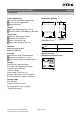
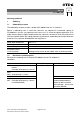
EMI suppression capacitors (MKP) B81123 Y1 / 500 V AC Typical applications Y1 class for interference suppression "Line to ground" applications Double insulation Dimensional drawing Climatic Max.
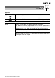
B81123 Y1 / 500 V AC Approvals Approval marks Notes: Standards EN 60384-14, IEC 60384-14 Certificate 138584 UL1414 UL 60384-14, CSA E60384-14 E97863 E97863 (approved by UL) Effective January 2014, only for EMI supression capacitors: – UL 60384-14 certification replaces both UL 1414 and UL 1283 standards. – CSA C22.2 No. 1 and CSA C22.s No. 8 are replaced by CSA E60384-14.
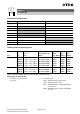
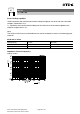
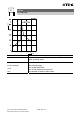
B81123 Y1 / 500 V AC Overview of available types Lead spacing 15 mm 22.5 mm CR (µF) 0.0010 0.0015 0.0022 0.0033 0.0047 0.0056 0.0068 0.010 Ordering codes and packing units Lead spacing CR mm 15 µF 0.0010 0.0015 0.0022 0.0033 0.0047 0.0056 0.0068 0.010 22.5 Max. dimensions w×h×l mm 5.0 × 10.5 × 18.0 6.0 × 11.0 × 18.0 7.0 × 12.5 × 18.0 8.5 × 14.5 × 18.0 9.0 × 17.5 × 18.0 7.0 × 16.0 × 26.5 8.5 × 16.5 × 26.5 10.5 × 18.5 × 26.
B81123 Y1 / 500 V AC Technical data Reference standard: IEC / UL 60384-14. All data given at T = 20 °C unless otherwise specified. Max. operating temperature Top,max +110 °C Dissipation factor tan δ (in 10-3) at 20 °C (upper limit values) Insulation resistance Rins or time constant τ = CR Rins at 20 °C, rel. humidity ≤ 65% (minimum as-delivered values) at 1 kHz 100 kHz 30 000 MΩ 1.0 5.0 DC test voltage 4800 V, 2 s The repetition of this DC voltage test may damage the capacitor.
B81123 Y1 / 500 V AC Pulse handling capability "dV/dt" represents the maximum permissible voltage change per unit of time for non-sinusoidal voltages, expressed in V/µs. "k0" represents the maximum permissible pulse characteristic of the waveform applied to the capacitor, expressed in V2/µs. Note: The values of dV/dt and k0 provided below must not be exceeded in order to avoid damaging the capacitor. dV/dt and k0 values Lead spacing dV/dt in V/µs k0 in V2/µs 15 mm 22.
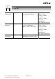
B81123 Y1 / 500 V AC Testing and Standards Test Reference Electrical Parameters IEC 60384-14 Robustness of terminations Resistance to soldering heat Conditions of test Voltage Proof: Between terminals: 4000 V AC, 1 min Terminals and enclosure: 4000 V AC, 1 min Insulation resistance, RINS Capacitance, C Dissipation factor, tan δ IEC 60068-2-21 Tensile strength (test Ua1) Tensile Wire diameter force 0.5 < d1 ≤ 0.8 mm 10 N 0.8 < d1 ≤ 1.
B81123 Y1 / 500 V AC Damp Heat Steady State IEC 60384-14 Test Ca 40 °C / 93% RH / 56 days Impulse test Endurance IEC 60384-14 3 impulses TB / 1.7 VR / 1000 hours, 1000 Vrms for 0.1 s every hour Passive flammability IEC 60384-14 Flame applied for a period of time B depending on capacitor volume Please read Cautions and warnings and Important notes at the end of this document. Page 8 of 19 No visible damage I∆C/C0 I ≤ 5% I∆ tan δ I ≤ 0.008, C ≤ 1 µF I∆ tan δ I > 0.
B81123 Y1 / 500 V AC Mounting guidelines 1 Soldering 1.1 Solderability of leads The solderability of terminal leads is tested to IEC 60068-2-20, test Ta, method 1. Before a solderability test is carried out, terminals are subjected to accelerated ageing (to IEC 60068-2-2, test Ba: 4 h exposure to dry heat at 155 °C).
B81123 Y1 / 500 V AC Immersion depth 2.0 +0/ 0.5 mm from capacitor body or seating plane Shield Heat-absorbing board, (1.5 ±0.5) mm thick, between capacitor body and liquid solder Evaluation criteria: Visual inspection ∆C/C0 tan δ Please read Cautions and warnings and Important notes at the end of this document.
B81123 Y1 / 500 V AC 1.3 General notes on soldering Permissible heat exposure loads on film capacitors are primarily characterized by the upper category temperature Tmax. Long exposure to temperatures above this type-related temperature limit can lead to changes in the plastic dielectric and thus change irreversibly a capacitor's electrical characteristics.
B81123 Y1 / 500 V AC Cautions and warnings Do not exceed the upper category temperature (UCT). Do not apply any mechanical stress to the capacitor terminals. Avoid any compressive, tensile or flexural stress. Do not move the capacitor after it has been soldered to the PC board. Do not pick up the PC board by the soldered capacitor. Do not place the capacitor on a PC board whose PTH hole spacing differs from the specified lead spacing. Do not exceed the specified time or temperature limits during soldering.
B81123 Y1 / 500 V AC Topic Safety information Soldering Do not exceed the specified time or temperature limits during soldering. Cleaning Use only suitable solvents for cleaning capacitors. Embedding of When embedding finished circuit assemblies in capacitors in plastic resins, chemical and thermal influences finished assemblies must be taken into account.
B81123 Y1 / 500 V AC Display of ordering codes for EPCOS products The ordering code for one and the same product can be represented differently in data sheets, data books, other publications and the website of EPCOS, or in order-related documents such as shipping notes, order confirmations and product labels. The varying representations of the ordering codes are due to different processes employed and do not affect the specifications of the respective products.
B81123 Y1 / 500 V AC Symbols and terms Symbol α αC A βC C CR ∆C ∆C/C ∆C/CR dt ∆t ∆T ∆tan δ ∆V dV/dt ∆V/∆t E ESL ESR f f1 f2 fr FD FT i IC English Heat transfer coefficient Temperature coefficient of capacitance Capacitor surface area Humidity coefficient of capacitance Capacitance Rated capacitance Absolute capacitance change Relative capacitance change (relative deviation of actual value) Capacitance tolerance (relative deviation from rated capacitance) Time differential Time interval Absolute temperat
B81123 Y1 / 500 V AC Symbol IRMS iz k0 LS λ λ0 λtest Pdiss Pgen Q ρ R R Ri Rins RP RS S t T τ tan δ tan δD tan δP tan δS TA Tmax Tmin tOL Top TR Tref tSL English (Sinusoidal) alternating current, root-mean-square value Capacitance drift Pulse characteristic Series inductance Failure rate Constant failure rate during useful service life Failure rate, determined by tests Dissipated power Generated power Heat energy Density of water vapor in air Universal molar constant for gases Ohmic resistance of discharg
B81123 Y1 / 500 V AC Symbol VAC VC VC,RMS English AC voltage Category voltage Category AC voltage VCD Vch VDC VFB Vi Vo Vop Vp Vpp VR Corona-discharge onset voltage Charging voltage DC voltage Fly-back capacitor voltage Input voltage Output voltage Operating voltage Peak pulse voltage Peak-to-peak voltage Impedance Rated voltage Amplitude of rated AC voltage R VRMS German Wechselspannung Kategoriespannung (Sinusförmige) Kategorie-Wechselspannung Teilentlade-Einsatzspannung Ladespannung Gleichspannung
Important notes The following applies to all products named in this publication: 1. Some parts of this publication contain statements about the suitability of our products for certain areas of application. These statements are based on our knowledge of typical requirements that are often placed on our products in the areas of application concerned.
Important notes 7. The trade names EPCOS, Alu-X, CeraDiode, CeraLink, CeraPad, CeraPlas, CSMP, CSSP, CTVS, DeltaCap, DigiSiMic, DSSP, ExoCore, FilterCap, FormFit, LeaXield, MiniBlue, MiniCell, MKD, MKK, MotorCap, PCC, PhaseCap, PhaseCube, PhaseMod, PhiCap, PQSine, SIFERRIT, SIFI, SIKOREL, SilverCap, SIMDAD, SiMic, SIMID, SineFormer, SIOV, SIP5D, SIP5K, TFAP, ThermoFuse, WindCap are trademarks registered or pending in Europe and in other countries. Further information will be found on the Internet at www.