SMT inductors SIMID series, SIMID 1210-100 Series/Type: B82422A*100 Date: September 2019 a~í~=pÜÉÉí ¤ TDK Electronics AG 2019. Reproduction, publication and dissemination of this publication, enclosures hereto and the information contained therein without TDK Electronics’ prior express consent is prohibited.
SMT inductors, SIMID series B82422A*100 SIMID 1210-100 Size 1210 (EIA) or 3225 (IEC) Rated inductance 0.0082 ... 100 μH Rated current 65 ...
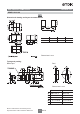
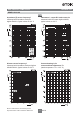
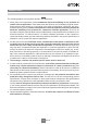
SMT inductors, SIMID series B82422A*100 SIMID 1210-100 Dimensional drawing and layout recommendation A B C D 2.7 1.15 2.1 4.4 Dimensions in mm Taping and packing Blister tape Reel Dimensions in mm A 09/19 180.0 +0/–3 330.0 r2.0 13.0 +0.5/–0.2 13.0 +0.5/–0.2 N 60.0 r1.0 W2 3 330 mm reel C W1 Please read Cautions and warnings and Important notes at the end of this document. 180 mm reel 8.4 +1.5/–0 14.4 max 75.0 +1.0/–3.0 8.4 +1.5/–0 14.
SMT inductors, SIMID series B82422A*100 SIMID 1210-100 Technical data and measuring conditions Rated inductance LR Measured with impedance analyzer Agilent 4294A or equivalent at frequency fL, 0.
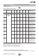
SMT inductors, SIMID series B82422A*100 SIMID 1210-100 Characteristics and ordering codes LR Tolerance PH fL Qmin MHz fQ IR Rmax MHz mA : fres, min Ordering code 1)2) ( 180-mm reel) MHz Core material: ceramic 0.0082 r5% 0.010 r10% 10 20 100 800 0.08 4000 B82422A3829+100 10 20 100 750 0.09 4000 B82422A3100+100 0.012 10 25 100 700 0.10 3500 B82422A3120+100 0.015 10 27 100 640 0.12 3000 B82422A3150+100 0.018 10 30 100 640 0.12 2500 B82422A3180+100 0.
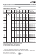
SMT inductors, SIMID series B82422A*100 SIMID 1210-100 Characteristics and ordering codes Tolerance LR PH fL Qmin MHz fQ IR Rmax MHz mA : fres, min Ordering code 1)2) ( 180-mm reel) MHz Core material: ferrite 1.0 r5% 1.2 r10% 1 20 7.96 380 0.34 320 B82422A1102+100 1 20 7.96 370 0.37 300 B82422A1122+100 1.5 1 20 7.96 340 0.50 270 B82422A1152+100 1.8 1 25 7.96 290 0.60 250 B82422A1182+100 2.2 1 25 7.96 270 0.75 125 B82422A1222+100 2.7 1 25 7.
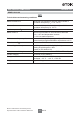
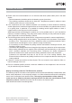
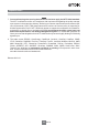
SMT inductors, SIMID series B82422A*100 SIMID 1210-100 Impedance |Z| versus frequency f measured with impedance analyzer Agilent E4991A, typical values at +20 °C Inductance L versus DC load current IDC measured with LCR meter Agilent 4285A, typical values at +20 °C Q factor versus frequency f measured with impedance analyzer Agilent 4294A/E4991A, typical values at +20 °C Current derating Iop/IR versus ambient temperature TA (rated temperature TR = +125 °C) Please read Cautions and warnings and Importa
Cautions and warnings ■ Please note the recommendations in our Inductors data book (latest edition) and in the data sheets. – Particular attention should be paid to the derating curves given there. – The soldering conditions should also be observed. Temperatures quoted in relation to wave soldering refer to the pin, not the housing.
Important notes The following applies to all products named in this publication: 1. Some parts of this publication contain statements about the suitability of our products for certain areas of application. These statements are based on our knowledge of typical requirements that are often placed on our products in the areas of application concerned.
Important notes 7. Our manufacturing sites serving the automotive business apply the IATF 16949 standard. The IATF certifications confirm our compliance with requirements regarding the quality management system in the automotive industry. Referring to customer requirements and customer specific requirements (“CSR”) TDK always has and will continue to have the policy of respecting individual agreements.