SMT current sense transformers EE 5.0 core Series/Type: B82801B a~í~=pÜÉÉí December 2012 Date: ¤ EPCOS AG 2012. Reproduction, publication and dissemination of this publication, enclosures hereto and the information contained therein without EPCOS’ prior express consent is prohibited.
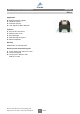
SMT current sense transformers B82801B EE 5.0 Application ■ ■ ■ ■ Switching power supplies Feedback control Overload sensing Load drop/shut down detection Features ■ ■ ■ ■ ■ Very low DC resistance Different turns ratios Small package Other pinning on request RoHS compatible Marking Middle block of ordering code Delivery mode and packing units ■ 16 mm blister tape, 330 mm reel ■ Carton packaging ■ Packing units: 900 pcs./reel; 7200 pcs.
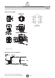
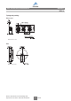
SMT current sense transformers B82801B EE 5.0 Dimensional drawing Dimensions in mm Application circuit and pinning Please read Cautions and warnings and Important notes at the end of this document.
SMT current sense transformers B82801B EE 5.0 Technical data and measuring conditions Frequency range 50 kHz ... 1 MHz Hi-pot 1000 V AC, 2 s (winding to winding) Inductance L (1-3) 100 kHz, 100 mV, @ +25 °C DC resistance Rmax Measured at +25 °C Sensed current The max. primary current of 20 A causes approx. +40 °C temperature rise Solderability t 99.9 Sn, lead-free. Or Sn96.5Ag3.0Cu0.
SMT current sense transformers B82801B EE 5.
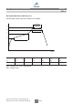
SMT current sense transformers B82801B EE 5.0 Taping and packing Blister tape Dimensions in mm Reel Dimensions in mm Please read Cautions and warnings and Important notes at the end of this document.
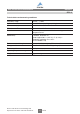
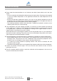
SMT current sense transformers B82801B EE 5.0 Recommended reflow soldering curve Pb-free solder material (based on JEDEC J-STD 020D) t3 T4 T3 t2 T2 T1 t1 IND0814-F T1 T2 T3 T4 T1 T2 T3 °C °C °C °C sec sec sec 150 200 217 245 <110 <90 20 ... 40 Max. time from +25 °C to T: 300 seconds Max. 3 reflow cycles Please read Cautions and warnings and Important notes at the end of this document.
Cautions and warnings ■ Please note the recommendations in our Inductors data book (latest edition) and in the data sheets. – Particular attention should be paid to the derating curves given there. Derating must be applied in case the ambient temperature in the application exceeds the rated temperature of the component.
Important notes The following applies to all products named in this publication: 1. Some parts of this publication contain statements about the suitability of our products for certain areas of application. These statements are based on our knowledge of typical requirements that are often placed on our products in the areas of application concerned.