CeraDiodes High-speed series Series/Type: Date: August 2008 © EPCOS AG 2008. Reproduction, publication and dissemination of this publication, enclosures hereto and the information contained therein without EPCOS' prior express consent is prohibited.
CeraDiodes High-speed series Features Very low capacitance values 0.6 up to 10 pF ESD protection to IEC 61000-4-2, level 4 Bidirectional ESD protection in one component No change in ESD protection performance at temperatures up to 85 °C (temperature derating) Low parasitic inductance Low leakage current Fast response time <0.
CeraDiodes High-speed series Electrical specifications and ordering codes Maximum ratings (Top,max = 85 °C) and characteristics (TA = 25 °C) Type Ordering code VDC,max VBR,min (1 mA) V V Array, 2/4 data + 1 supply, 0506, SOT-666 CDA3C05GTH B72755D0050H062 5.6 120 Array, 2/4 data + 1 supply, 1012, SOT-23 6L CDA6C05GTH B72735D0050H062 5.
CeraDiodes High-speed series Dimensional drawings Single device Dimensions in mm Case (inch) 0201 size (mm) 0603 Min. l 0.57 w 0.27 h 0.27 k 0.1 Max. 0.63 0.33 0.33 0.2 0402 1005 Min. 0.85 0.4 0.4 0.1 0603 1608 Max. Min. 1.15 1.45 0.6 0.7 0.6 0.7 0.3 0.1 1003 2508 Max. Min. 1.75 2.34 0.9 0.7 0.9 0.7 0.4 0.13 Max. 2.74 0.9 0.9 0.75 Array devices 4-fold array 2/4 data + 1 supply Dimension in mm Case size (inch) (mm) 0506 1216 0508 1220 0612 1632 1012 2532 Min. Max. Min. Max. Min. Max.
CeraDiodes High-speed series Recommended solder pads Single device Dimensions in mm Case size (inch) (mm) 0201 0603 0402 1005 0603 1608 1003 2508 A 0.3 0.6 1.0 0.8 B 0.25 0.6 1.0 0.8 C 0.3 0.5 1.0 1.45 Array devices 4-fold array 2/4 data + 1 supply Dimensions in mm Case size (inch) (mm) 0506 1216 0508 1220 0612 1632 1012 2532 A 0.36 0.35 0.5 0.7 B 0.84 0.9 0.7 1.0 C 0.62 0.4 1.2 1.4 E 0.50 0.5 0.76 0.
CeraDiodes High-speed series Pin configurations Single device Pin P1 Description GND P2 I/O line Pin P1 Description GND P2 GND P3 GND P4 GND P5 I/O line 1 P6 I/O line 2 P7 I/O line 3 P8 I/O line 4 Pin P1 Description I/O line 1 P2 GND P3 I/O line 2 P4 I/O line 3 P5 VDC P6 I/O line 4 Array devices 4-fold array 2/4 data + 1 supply Please read Cautions and warnings and Important notes at the end of this document.
CeraDiodes High-speed series Termination Single device Array device Please read Cautions and warnings and Important notes at the end of this document.
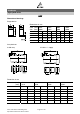
CeraDiodes High-speed series Delivery mode EIA case size Taping 0201 0402 0402 0402 0506 0508 0603 0603 0603 0612 1003 1012 Cardboard Cardboard Cardboard Cardboard Blister Cardboard Cardboard Cardboard Cardboard Blister Cardboard Blister Reel size mm 180 180 180 180 180 180 180 180 180 180 180 180 Please read Cautions and warnings and Important notes at the end of this document. Packing unit pcs.
CeraDiodes High-speed series 1 Taping and packing for chip and array CeraDiodes 1.1 Cardboard tape (taping to IEC 60286-3) Dimensions in mm Case size (inch) (mm) 0201 0603 0402 1005 0603 1608 1003 2508 0508 1220 Tolerance Compartment width A0 0.38 ±0.05 0.6 0.95 1.0 1.6 ±0.2 Compartment length B0 0.68 ±0.05 1.15 1.8 2.85 2.4 ±0.2 Sprocket hole diameter D0 1.5 ±0.1 1.5 1.5 1.5 1.5 +0.1/ 0 Sprocket hole pitch P0 4.0 ±0.11) 4.0 4.0 4.0 4.0 ±0.
CeraDiodes High-speed series 1.2 Blister tape (taping to IEC 60286-3) Dimensions in mm 0506 1216 Case size (inch) (mm) 0612 1632 1012 2532 Tolerance Compartment width A0 1.5 1.9 2.8 ±0.2 Compartment length B0 1.8 3.5 3.5 ±0.2 Compartment height K0 0.8 1.8 1.8 max. Sprocket hole diameter D0 1.5 1.5 1.5 +0.1/ 0 Compartment hole diameter D1 1.0 1.0 1.0 min. Sprocket hole pitch P0 4.0 4.0 4.0 ±0.11) Distance center hole to center compartment P2 2.0 2.0 2.0 ±0.
CeraDiodes High-speed series 1.3 Reel packing Dimensions in mm Dimensions Tolerance Dimensions Tolerance Reel diameter A 180 +0/ –3 330 ±2 Reel width (inside) W1 8.4 +1.5/ –0 8.4 +1.5/ –0 Reel width (outside) W2 14.4 max. 14.4 max. Package: 8-mm tape Reel material: Plastic 1.
CeraDiodes High-speed series Soldering directions 1 Reflow soldering temperature profile Recommended temperature characteristic for reflow soldering following JEDEC J-STD-020D Profile feature Preheat and soak - Temperature min - Temperature max - Time Average ramp-up rate Liquidous temperature Time at liquidous Peak package body temperature Time (tP)3) within 5 °C of specified classification temperature (Tc) Average ramp-down rate Time 25 °C to peak temperature Tsmin Tsmax tsmin to tsmax Tsmax to Tp TL
CeraDiodes High-speed series 2 Soldering guidelines The use of mild, non-activated fluxes for soldering is recommended, as well as proper cleaning of the PCB. The components are suitable for reflow soldering to JEDEC J-STD-020D. 3 Solder joint profiles / solder quantity 3.1 Cement quantity The component is fixed onto the circuit board with cement prior to soldering. It must still be able to move slightly.
CeraDiodes High-speed series 3.3.1 Solder joint profiles for nickel barrier termination Good and poor solder joints caused by amount of solder in infrared reflow soldering Please read Cautions and warnings and Important notes at the end of this document.
CeraDiodes High-speed series 4 Solderability tests Test Standard Test conditions / Sn-Pb soldering Test conditions / Pb-free soldering Criteria / test results Wettability IEC Immersion in 60068-2-58 60/40 SnPb solder using non-activated flux at 215 ±3 °C for 3 ±0.3 s Covering of 95% of end termination, checked by visual inspection IEC Immersion in 60068-2-58 60/40 SnPb solder using mildly activated flux without preheating at 255 ±5 °C for 10 ±1 s Immersion in Sn96.5Ag3.0Cu0.
CeraDiodes High-speed series 5 Notes for proper soldering 5.1 Preheating and cooling The average ramp-up rate must not exceed 3 °C/s. The cooling rate must not exceed 8 °C/s. 5.2 Repair / rework Manual soldering with a soldering iron must be avoided, hot-air methods are recommended for making repairs. 5.3 Cleaning All environmentally compatible agents are suitable for cleaning. Select the appropriate cleaning solution according to the type of flux used.
CeraDiodes High-speed series 5.7 Placement of components on circuit board It is of advantage to place the components on the board before soldering so that their two terminals do not enter the solder oven at different times. Ideally, both terminals should be wetted simultaneously. 5.8 Soldering caution Sudden heating or cooling of the component results in thermal destruction by cracks.
CeraDiodes High-speed series Symbols and terms CeraDiode Semiconductor diode Cmax Ctyp Maximum capacitance Typical capacitance IBR Ileak IPP IPP IR, IT IRM IPP IP, IPP (Reverse) current @ breakdown voltage (Reverse) leakage current Current @ clamping voltage Peak pulse current PPP PPP Peak pulse power Top Tstg VBR VBR,min Vclamp Vclamp,max VDC Operating temperature Storage temperature VBR Vcl, VC VRM, VRWM, VWM, VDC VDC,max VESD,air VESD,contact Vleak VRM, VRWM, VWM, VDC - *) - *) IF IRM, IR
Important notes The following applies to all products named in this publication: 1. Some parts of this publication contain statements about the suitability of our products for certain areas of application. These statements are based on our knowledge of typical requirements that are often placed on our products in the areas of application concerned.