
User manual

Stand: Februar 2011
Z 385 engl
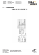
1. Getting started guide: GS24S/xx-360 with 9-pole screw terminal block
1. Select operating mode on J1 (the default internal mode is Standard, which is obtained
by setting J1 on I).
Select J2 (Standard is internal RF).
2. Connect the following digital input
(Connect terminal 7 to terminal 9; Input for enabling the regulator when J2 is set on
External).
3. Connect the following analogue inputs
Input N set point (terminal 8) voltage 0 to + 10 V or potentiometer (10kOhm)
between terminal 4 and terminal 7, tap from terminal 8.
4. Connect DC motor to terminals 5 and 6.
5. Connect power supply to terminal 3 (-) and terminal 2 (+) (approx. 20 – 36 V DC).
6. Proceed to energise the power supply.
7. LED (power on) lights up on circuit board.
8. The motor turns and the rotation speed can be adjusted via the voltage on terminal 8
(n set-point).