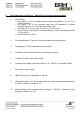
Technical specification 4-Q-motor control unit digital type DLR 24/xx - 466 Table of contents 1. Brief instruction DLR24/xx-466 with 19-pin spring clamp terminal 2. General information 2.1 Technical features 2.2 Accessories 3. Technical data 4. Connection 4.1 Control connections 4.2 Connection plan 5. Setting parameters 5.1 Overview DIP switch 6. Scale drawings 6.1 DLR 24/xx/P 6.2 DLR 24/xx/M 6.3 DLR 24/xx/G 7. Notes and recommendations on using EPH motor control cards 7.1 Delivery 7.
Stand: Juni 2009 Z 319 engl.
1. Brief instruction DLR 24/xx - 466 with 19-pin spring clamp terminal 1. Select modes: • put jumper 1 on 1-2 for internal reference value (potentiometer 1) or on 2-3 for external reference. • put jumper 2 on 1-2 for reference value max. 5V (important for internal reference value) or on 2-3 for 10V target value input. • put jumper 3 on 1-2 for 12V motor or on 2-3 for 24V motor.
2. General information The digital, load-independent 4-Q motor speed controllers of the DLR 24 /xx-466 series are cost-effective compact devices with the dimensions of 140 x 125 x 52 mm for stepless speed control for any type of brushed DC motors in the low voltage range up to a maximum of 10 A motor power. The input voltage range is from 10 to 36V DC, this allows direct battery or on-board power supply. A DC power supply of the SNT 24/xx series can also be used.
3. Technical data type DLR 24/ 05 DLR 24/ 10 Supply Voltage 10-36V DC 10-36V DC Armature voltage UA 0 - 12/24V DC 0 - 12/24V DC Armature current IN 0 - 5A 0 - 10A Mechanical power Pab approx. 75W approx.
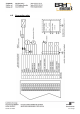
4.2 Stand: Juni 2009 Connection plan Z 319 engl.
5. Setting parameters ref. Speed value: external via 0..10V DC interface or external via 0..5V DC interface or external 10kOhm potentiometer (see Connection plan) or usage of the internal potentiometer 1 (n ref.) Controller enable: for activation of the directions (see Connection plan) Motor voltage: limitable to max. 12V DC or 24V DC (see table, max. 90% of the power supply) jumper JP1 JP2 JP3 position 1-2 ref. Speed value intern ref.
Stand: Juni 2009 Z 319 engl.
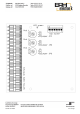
5.1. Overview DIP switch Different modes are selectable by using the DIP-switch (mode changes works only, when the power supply is turned off and on). Off Controller enable not inverted (terminals 15 and 16 must be connected, for working motor in the wanted direction) DIP 1 ON Controller enable inverted (terminals 15 and 16 must not be connected, for working motor in the wanted direction) DIP 2 Off ref. Speed enable not inverted (terminal 18 must be connected, for a working ref.
6. Scale drawings 6.1. DLR 24/xx/P Stand: Juni 2009 Z 319 engl.
6.2. DLR 24/xx/M Stand: Juni 2009 Z 319 engl.
6.3. DLR 24/xx/G Stand: Juni 2009 Z 319 engl.
7. Notes and recommendations on using EPH motor control cards Notes and recommendations on the use of EPH motor control cards in electric drive systems in accordance with the respectively applicable EC machine directives 98/37/EG, EMC directive 2004/108/EG and low voltage directive 2006/95/EG In its application the machine directive required the CE labelling of complete machines only.
7.1. Delivery On receipt or unpacking of the device immediately examine it for transport damage. In the event of damage, immediately contact the freight forwarder, initiate a detailed survey. This also applies if the packaging is not damaged. 7.2. Installation, launch and safety measures ESD-protection / Installation instructions Attention during installation of the electronic board! It must be warranted on your part that there is sufficient ESD-protection.
Beware, danger of life! Parts of the controller card are on the intermediate circuit voltage (up to 48V DC) and result in live voltage for about 5 minutes after deactivating the current. Touching the terminals, lines and device parts can cause serious injury or death! 7.3. EMC measures Ensure that the controller devices are suitable for use in the required EMC environment.
• Only shielded lines may be used (industry lines with shield mesh wire). • Ensure that the protection line connection (PE) is connected correctly. The mains filter must be connected to the earth potential. • Using the accessories: Input reactor type EPH : EDMB.20.0 001 the EN 55011/1998+A1+A2 standard (limit class A) is complied with. 7.4.
8.
Notes: _____________________________________________________________________________________ _____________________________________________________________________________________ _____________________________________________________________________________________ _____________________________________________________________________________________ _____________________________________________________________________________________ ______________________________________________________________________
Notes: _____________________________________________________________________________________ _____________________________________________________________________________________ _____________________________________________________________________________________ _____________________________________________________________________________________ _____________________________________________________________________________________ ______________________________________________________________________