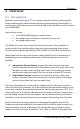
Overview 2 Overview 2.1 Introduction Epiphan’s Lecture Recorder x2™ is a compact, portable solution combining both Ethernet-based audio-video broadcast streaming and recording functionalities. It transfers up to 30 frames per second of visual and audio information with resolution up to 1920x1080. Input sources can be: a DVI/VGA/HDMI display or camera source an analog camera (S-Video or composite) source, and an analog audio source.
Physical Attributes When configured for dual streaming, the Lecture Recorder x2 is being used for the simultaneous broadcasting from both a DVI/VGA/HDMI input source and either a composite or S-Video analog input source if this is not the case of publishing stream or multicast RTP stream. In addition to a single URL showing both streams, viewers may obtain two different URLs one for each of the input sources making up the broadcast.
Physical Attributes Figure 1 Front View of the Lecture Recorder x2 Below is a table summarizing the connectors and indicators found on the front panel of the Lecture Recorder x2. Table 1 Summary of the Front Panel's connectors and Indicators Number 1 Name Factory Reset Button Description Resets the Lecture Recorder x2 back to its factory configuration defaults.
Physical Attributes 4 USB port 5 S-Video input 6 DVI In 7 Audio In blinking. Green and blue LEDs: When the Lecture Recorder x2 device first starts up, the blue LED lights up. A few seconds later the green LED lights up. After about another 20 seconds the blue LED turns off, leaving the green LED on indicating that the Lecture Recorder x2 has started up and can start capturing images.
Physical Attributes Figure 2 The Lecture Recorder x2's Rear Panel Below is a chart detailing the connectors found on the rear panel. Table 2 Summary of Connectors on the Rear Panel Number 8 Connector Audio Out Description Connects audio equipment, such as headphones or speakers, to confirm whether the audio stream is currently being captured by the Lecture Recorder x2. 9 DVI Out 10 USB port Used to verify and confirm that the connected video source from DVI In port is being received.
11 RJ45 Ethernet Physical Attributes above. Primary 10/100 Base-T RJ-45 Ethernet network port to connect the Lecture Recorder x2 to an Ethernet network. The Lecture Recorder x2’s Ethernet port is auto-sensing. Power over Ethernet is used to power the Lecture Recorder x2. If the intended network connection does not provide power over Ethernet, use the Power over Ethernet Injector and this port in order to power the device. 3.
Physical Attributes 3.2.2 VGA to DVI Cable Connects a VGA source to either of the Lecture Recorder x2’s DVI ports. This cable is included with the Lecture Recorder x2. Figure 4 VGA to DVI cable 3.2.3 DVI to DVI Cable Connects a DVI source to either of the Lecture Recorder x2’s DVI ports. This cable is included with the Lecture Recorder x2.
Physical Attributes Figure 5 DVI to DVI cable 12 Lecture Recorder x2 User Guide
Physical Attributes 3.2.4 S-Video Cable Connects an S-Video output source to the Lecture Recorder x2’s S-Video port. Figure 6 S-Video cable 3.2.5 Composite to S-Video Cable Connects a composite output analog video source to the Lecture Recorder x2’s SVideo port. This cable is included with the Lecture Recorder x2.
Physical Attributes Figure 7 Composite to S-Video cable HDMI to DVI Adapter Connects an HDMI source to either of the Lecture Recorder x2’s DVI ports. This adapter is included with the Lecture Recorder x2. 3.2.6 Figure 8 HDMI to DVI adapter 3.2.7 RJ-45 Male Connects the Lecture Recorder x2 to an Ethernet network.
Getting Started Figure 9 RJ-45 Male cable 3.2.8 Power over Ethernet (PoE) Injector The Lecture Recorder x2 incorporates a Power over Ethernet (PoE) technology. PoE delivers both data and electrical power to an Ethernet enabled device using a single Ethernet cable. This eliminates the need for the Lecture Recorder x2 to be situated close to a power outlet. This allows more freedom in its placement. PoE injectors supply or inject direct current (DC) power through network cables to power network devices.
Getting Started Regardless of the power source once connected, the Lecture Recorder x2 now powers up. Its power and activity LEDs will now light up following their start up sequence. 4.2 Confirm Input Signals are Received Confirming that the input signals are being received by the Lecture Recorder x2 can be done once the Lecture Recorder x2 has been powered on and the input sources have been started. First, check that the Lecture Recorder x2’s red LED is blinking.
Getting Started 4.2.3 Checking the Analog Audio Signal As with any input source plugged into the Lecture Recorder x2’s DVI input port, any audio input being sent to the Lecture Recorder x2 via its Analog Audio input port can be verified. To listen to the audio being captured by the Lecture Recorder x2, plug in a stereo speaker or headsets into the Analog Audio out port. 4.
Getting Started Linux – the Avahi implementation used for service discovery is shipped with most Linux distributions. Therefore most probably your device will be accessed without any additional installations. However you are recommended to address your administrator for the details first. The simplest way to access Web Admin interface of your Lecture Recorder x2 in the local network is to type the following string in the address bar of your web browser: .
Getting Started 1. 2. 3. Start a web browser on any workstation connected to the same network as the Lecture Recorder x2. Browse to the Lecture Recorder x2. http:///admin The IP address of the Lecture Recorder x2 can be obtained using any of the following methods: a. The Epiphan Network Utility b. The EpiphanTouch app c. From the network administrator d. Using the Factory Default static IP address.
4. 5. 6. Getting Started System monitoring. This would involve retrieving any system statuses and retrieving the solid state memory status. Upgrading the System Firmware from Epiphan Support. New firmware is released to fix known problems or to add new features. Perform network diagnostics. As a default factory setting, the administrator user does not come with a password but it is recommended that a password is configured as early as possible for security reasons. 4.5.
Getting Started Figure 10 Web Admin Interface's Main Menu 21 Lecture Recorder x2 User Guide
Getting Started The following table briefly describes each of the options on the Web admin Interface’s main menu. Table 3 Web admin Interface’s Main Menu Options Stream Setup Publish Stream Stream Branding UPnP Frame Grabber Audio Automatic File Upload FTP Server Network Date and Time Access passwords Serial Port Branding Maintenance Disk Check Firmware Upgrade Info Disk Status 22 Change the stream settings.
Signal Flow Diagrams 5 Signal Flow Diagrams A series of diagrams below depicts how signal capture, encoding, streaming and recording is performed.
Video Formats and Standards Figure 13 Data Streaming Flow 6 Video Formats and Standards The Lecture Recorder x2 supports broadcasting of various standards and formats. The choice of video format will depend on the broadcast content and performance requirements. For example, Motion JPEG does not support audio from an external source. It also depends on how the intended viewers are planning to receive and play the broadcast.
Signal Capture The Adobe Flash Video stream type is proprietary but is supported on most web browsers and on many media players including the VLC Media Player. This stream type supports the H.264 standard. This video supports analog audio from an external source. The Advanced System Format (ASF) stream type also called Advanced Streaming format, can be viewed with the Windows Media Player or the VLC Media Player. Additional codecs may need to be installed to view ASF files. This stream type supports H.
Signal Capture 7.1.1 Connecting DVI, VGA or HDMI Input Sources All DVI, VGA or HDMI input sources are connected to the Lecture Recorder x2 using the DVI input port. How this connection is made and using which cable is dependent on the input source. DVI input sources are connected using the DVI to DVI cable, Figure 5 DVI to DVI cable. VGA input sources are connected using the VGA to DVI cable, Figure 4 VGA to DVI cable.
Signal Capture Normally, making manual image adjustments should not be necessary. This means that there are no default Frame Grabber adjustment settings. However, special requirements may exist that produce image quality problems that can only be fixed by making image adjustments. The Frame Grabber adjustments page within the Web admin interface contains most of the information needed to make image adjustments.
Signal Capture Figure 14 Frame Grabber Adjustments 28 Lecture Recorder x2 User Guide
Signal Capture The table below discusses all options found on the Frame Grabber Adjustment page. Table 4 Frame Grabber Adjustment Options Use signal from Interval between VGA signal autoadjustments, sec Vertical shift Horizontal shift Phase PLL adjustment Offset 29 Specify the the native colour space of the signal source, either RGB or YUV.
Gain Aspect ratio Select EDID file Channel Setup achieve the best results. Compensate for a large change to one by making a large change to the other, but setting both offset and gain to high values can result in poorer video quality. Use the offset and gain controls together to optimize image quality. Increasing the gain amplifies weak signals but also increases noise. Balance offset and gain values to achieve the best quality image.
Channel Setup 1. Select the required channel. 2. Click the Stream Setup option. 3. Click an arrow in the Codec field. 4. Select the required codec from the drop-down list. The following values are available for selection: H.
Enhanced compatibility mode (h.264 slicing for RTP) Channel Setup This parameter can be set for the H.264 codec only. This parameter provides operating stability if the transmitted video/audio stream is not quite supported by the viewer’s equipment. When this parameter is activated, each picture is subdivided into one or more slices. The slice is given increased importance in H.264 as the basic spatial segment that is independent from its neighbours.
Channel Setup Table 6 DVI Channel settings Show time label Frame size Key frame interval Limit frame rate Bitrate If the video needs to be time labeled or timestamped, this parameter allows how the date and time will be displayed. Click on Show substitutions and use the Format substitutions commands to select the desired date and time format. The commands are described in table 7 below. If time labeling is not required, leave this field blank.
Channel Setup MJPEG only) improve the quality of the broadcast. Table 7 Format Substitutions Commands Command Value date year month (as 01) month (as Jan) month (as January) day of month weekday (as Thu) weekday (as Thursday) time hour minute second ms %F %G %m %b Example (27/09/2012 10:50:45.378) 2012-09-27 2012 09 Sep %B September %d %a 27 Thu %A Thursday %T %k %M %S %#m 10:50:45 10 50 45 378 8.
Channel Setup Figure 17 Video Channel Settings The table below outlines the video channel video configurable options. Table 8 Video Channel Settings Enable video channel Picture-in-picture layout Background color 35 Select this checkbox to enable the recording of the video signal from the analog video source. Use these radio buttons to specify how the DVI/VGA and S-Video/composite video sources are streamed when both are being used.
Video signal type Frame size Show time label Key frame interval Limit frame rate Bitrate Channel Setup Select the video signal type coming from the SVideo source: - S-Video Composite Select a Frame size from the drop-down list to limit the width and height of the video image. If the analog video source is sending resolutions larger than the resolution limit they will be scaled to the resolution limit. Limiting the frame resolution can help to reduce bandwidth usage.
Channel Setup Figure 73 Correlation Between FPS and Bitrate Values at Resolution 1280x720 Figure 74 Correlation Between FPS and Bitrate Values at Resolution 1920x1080 Figure 75 Correlation Between FPS and Bitrate Values at Resolution 640x480 8.4 Picture In Picture Layouts If you are capturing video from two video sources, you can create a layout for the recording/broadcast, i.e. specify how two videos are positioned on a screen relative to each other.
Channel Setup Figure 18 Setting Background Color 8.5 Common settings The following common parameters can be additionally specified: Table 9 Common settings Rate control mode Used for H.264 and MPEG4 codecs. It specifies the bitrate encoding for the signal. Select one of the following: - Low Delay Means Constant Bitrate Encoding (CBR) will be used. CBR is useful for streaming multimedia content on limited capacity channels since it is the maximum bit rate that matters, not the average.
RTSP streaming port Channel Setup streaming is being used and there are two streams, this value remains the same for both of the URLs being used. The port number cannot be lower than 500. In case of RTSP streaming this value is not considered. The number of the port being used to stream the RTSP broadcast. This value would be used along with the URL to access the broadcast.
Channel Setup Table 10 Audio settings Enable audio Audio format Audio channels Audio bitrate Select this checkbox to enable audio for the broadcast. You can select the following audio formats: MP3 – a common audio format for consumer audio storage Raw PCM (Pulse Code Modulation) – a standard form for digital audio in computers as well as other uses such as digital telephone systems G.711 – an ITU-T standard for audio companding. It is a very commonly used waveform codec.
Streaming 9 Streaming There are several decisions that need to be made when planning the creation of a broadcast, besides its exact content of the broadcast. Will the broadcast include an audio component coming from an analog audio source? What video format to use, what video standard to use, how to stream the broadcast are all questions that have to be answered when creating a broadcast.
Streaming Figure 21 Protocol Stack Diagram How the broadcast will be delivered to its viewers depends on the number of intended viewers and where the viewers are in relation to where the broadcast is originating. Are they on the same LAN or will they be accessing the broadcast from an external network? The answers to the above questions will help decide the delivery method of the broadcast.
Streaming 9.2 Using a Content Distribution Network A content delivery network (CDN) is a system of computers or servers that ingest an incoming stream source and rapidly provides this content to numerous users by duplicating the content on multiple servers and directing the content to users. CDN distributes a heavy load of traffic to multiple locations in order to avoid congestion on a network that could impact a user’s Internet experience.
Streaming Figure 22 Using a CDN Service Increases Scalability of Concurrent Viewers The Publish Stream functionality allows for directing captured video and audio to servers or clients using one of the available stream modes. The following options are available: - Disabled. If this option is enabled, you cannot send multicast RTP stream, perform CDN broadcasting or stream video to Epiphan’s portal. - to xxxxx.epiphan.tv. This option allows for streaming video to the Epiphan’s portal.
Streaming In the Independent Channel Stream mode it is not possible to publish both input sources using any of the Publish Stream options. Whether you need to send multicast RTP stream or publish video through CDN, it can be done only for the DVI input source. The Publish Stream functionality is available only for the H.264 video codec. 9.2.1 Using Epiphan.tv Portal for Streaming To set up and perform streaming via Epiphan.tv portal: 1. 2. 3.
Streaming Figure 24 System Message in Case of Excessive Bitrate Speed Figure 25 System Message after Setting H.264 codec and Reducing Bitrate Now connection through the media tunnel is established. The Lecture Recorder x2 starts streaming to the Epiphan’s portal – epiphan.tv. It is required to set up audio format as MP3 when streaming through the epiphan.tv. This setting is performed in the control interface’s Stream Setup section (see Select Audio Format).
7. 8. 9. Streaming Click Switch to button and select a plugin for viewing the stream. If you need to embed the stream into your web page, click Embed to obtain the code. Click Direct URL to obtain the list of URLs for different types of broadcasting.
Streaming Figure 28 Code for Stream Embedding Figure 29 Listing of Direct URLs Alternatively you can configure Lecture Recorder x2 to stream their content through epiphan.tv directly on the portal. To view the stream directly on the portal: 1. 2. 3. Type http://epiphan.tv in the address bar of your browser. Enter serial number of Lecture Recorder x2. It is displayed in the Info section of the Web admin interface. Click the Go! button. Using Epiphan’s Partners as CDN Providers for Streaming 9.2.
2. 3. 4. 5. 6. 7. Streaming Enter the host/server name. For example, 172.20.1.50. Enter the number of port which is used for streaming to server. Usually for RTSP streaming it is port 554. In the Mount point field enter the full path to locate an SDP file on server. This path is provided by the CDN provider. The RTSP protocol uses UDP or TCP as transport layers. If your CDN service requires TCP as a transport layer, select the Use TCP for RTP stream check box.
Streaming Sending multicast streams requires equipment that supports multi-casting, configuring your network and enabling specific multicasting features on the Lecture Recorder x2. Multicast architectures are used predominantly within a high bandwidth corporate LAN and not on Internet based architectures. Multicast RTP streaming is not usually propagated outside the LAN though it may be propagated through VPNs connecting several LANs. Multicast transmission is available during RTP streaming.
Streaming Figure 31 RTP/UDP Push Functionality 9.2.3.1 RTP/UDP Push streaming for the MPEG-TS file format The Web interface allows you to set up the MPEG-TS stream using MPEG-TS for RTP/UDP Push and MPEG-TS for UDP Push options. These options are used, for example, when you need to add a VGADVI Recorder’s stream to an IP TV or set-top box’ playlist. To use the RTP/UDP Push streaming, you must configure the following streaming settings in the Web Admin interface: Video codec Audio codec H.
Streaming Figure 32 MPEG-TS UDP Push Functionality To view the stream you need a link: rtp://@ip:port (for example, rtp://@226.63.45.23:6000). To get the link for the stream, select the Info section of the Web admin interface and view the Stream Info pane. 9.2.3.2 UDP Push streaming for the MPEG-TS file format To configure UDP transporting for the MPEG-TS stream, select using MPEG-TS for UDP Push from the drop-down list.
Streaming Figure 33 MPEG-TS RTP/UDP Push Functionality To view the stream you need a link: udp://@ip:port (for example, rtp://@226.63.45.23:6000). To get the link for the stream, select the Info section of the Web admin interface and view the Stream Info pane. 9.3 UPnP The VGADVI Recorder supports a set of networking protocols named Universal Plug and Play (UPnP).
2. 3. 4. 5. 6. Streaming If necessary, in the UPnP section use the Server field to name the media server (VGADVI Recorder). You can use the following characters: A-Z, a-z, 0-9, _, :, @, ^, #, -. {}, [], (). In the UPnP section select the Share live video through UPnP checkbox if you want to share live video streaming only. Select the Share recorded files through UPnP checkbox if you want to share recorded files only.
Streaming Figure 35 Live Streams and Recorded Files Folders 8. Select the folder and the required stream or recorded file. All files are sorted by date (Last 24 hours, last month, last week, older).
Streaming Figure 37 Selecting Live Stream 9.4 Viewing Streaming Video The Lecture Recorder x2 may capture audio and video at resolutions up to 1920 x 1200. The resolution of the broadcast may exceed this value, for example, in case of analog video broadcasting. Viewers can access the broadcasted video streams with a web browser that supports Motion JPEG, MPEG4 or Flash Video/H.264 compression or with a media player that is compatible with the stream format being transmitted.
Streaming used to view video from both DVI and S-Video inputs. The Live View button (see the section Using the Web Admin Interface’s Live View Feature) performs the same action. URLs for the broadcast coming from the DVI port are named as shown below: http:// (or rtsp://)***.***.***.***:***/stream.*** URLs for the broadcast coming from the S-Video port are named as shown below: http:// (or rtsp://)***.***.***.***:***/stream_video.
Streaming Figure 38 URLs of the Broadcast Displayed in the Stream Info Section 9.4.3 Using the Web Admin Interface’s Live View Feature The second method for retrieving the desired broadcast URLs is to use the Web Admin interface’s Live View Feature. This feature not only shows the current broadcast to the administrator but also provides the broadcast URLs. By clicking on the Live View button from the main menu, a preview of the current broadcast’s videos appear in the web browser.
Streaming Figure 39 A Broadcast with its URL Displayed Under the Broadcast Image 9.5 Viewing a Broadcast with a Browser If the administrator has configured a viewer password, participants must obtain the password in order to log in. The administrator will also provide the IP Address or the URL to be used by the viewer’s browser. To log in to view the broadcast using a browser: 1. Start any web browser. 2. Browse to the IP address of the Lecture Recorder x2’s broadcast stream.
Streaming Figure 40 Viewing a Broadcast Using a Web Browser 9.6 Viewing a Broadcast with a Media Player If the administrator has configured a Viewer password, participants must obtain the password in order to log in. The administrator will also provide the IP Address or the URL to use within the media player. To log in to view a stream using a media player: 1. 2. 3. 4. 60 Launch the media player. Use the Menu bar to open the URL dialog box and enter the URL address of the stream.
Streaming 9.7 Compatibility Information This section provides information on compatibility of video streaming formats and player which is necessary for streaming video. The Lecture Recorder x2 can stream video using Flash (H.264), ASF (MPEG4 or H.264 codecs), Motion JPEG or RTSP (MPEG4 or H.264 codecs). A quick definition of these video streaming methods and the type of application that a viewer would use to watch that particular video stream is now provided.
Video codec selected H.264 H.264 H.264 H.264 H.264 MPEG-4 MPEG-4 MPEG-4 MPEG-4 MPEG-4 MJPEG Audio codec selected No audio codec LPCM G.711 MP3 AAC No audio codec LPCM G.711 MP3 AAC No audio codec RTSP FLV ASF MPEG-TS Streaming MJPEG + + + + - + + + + + + + + - + + + + + + + - - + + + + - - + + + + - - + The following table displays the compatibility between the video/audio codecs and the file formats during data recording. Video H.264 H.264 H.264 H.264 H.
Recording 10 Recording The Lecture Recorder x2 captures video and audio data which can be encapsulated in a file or files and recorded. The Web admin interface provides the administrator and operator users with the ability to start, stop and configure the recording. Additionally, recorded video files might need to be downloaded or copied to another device for archiving purposes; also they might need to be deleted in order to manage disk space on the Lecture Recorder x2.
Recording you should select the H.264 codec with Video encoding profile set as Main or High. In this mode you are unable to publish both streams using the Publish Stream function. Also note that in this mode only a URL for the broadcast coming from the DVI input can be used for publish streaming. To decide which mode to select you need to know how you will use the Lecture Recorder x2.
Recording Figure 41 Select Recording Format 1. 2. Use the File Type drop-down list to select the recording format. The following file formats are available: o MOV o AVI o MPEG-TS Click Apply. 10.3 Changing Time and Size Limits The Lecture Recorder x2 can record the channel to one or more files according to time and file size limit parameters. It will automatically create and start recording to a new file whenever either limit is reached. To specify the time and file size limit parameters: 1. 2.
Recording Figure 42 Changing Time Limit and Size Limit 3. Click Apply. Table 11 Time and file size limit parameters Time limit Size limit Specify the maximum amount of time to record to a file. When either the time limit or the size limit is exceeded, the system starts recording data to a new file. Specify the maximum size of the recorded file. When either the time limit or the size limit is exceeded, the system starts recording data to a new file. 10.
Recording 10.5 Starting and Stopping Recording The recorder status is shown in the Web Admin interface. It is located on the left hand side of the screen above the Web Admin interface’s main menu. The ability to manage a recording with the Web Admin interface is done using these buttons. Note that the format of the recorded file is specified clicking the Recorded Files button and selecting the required File Type value.
Recording 10.6 Viewing the Current Recording Viewing the broadcast as it is being recorded is performed by doing the following: Select Live View from the Web Admin Interface’s main menu. A preview of the broadcast that is currently being recorded appears in the web browser. The preview is exactly the same as what is being recorded. If the broadcast is coming from two sources through the DVI and S-Video connectors, both will be seen. Under the broadcast screen the system displays the broadcasts' URLs.
Recording 10.8 Recorded Files The Recorded Files section lists all of the video files recorded by the Lecture Recorder x2 and that are saved on it. It is accessed by clicking the Recorded Files button from the Web admin interface’s main menu. If the signals are captured from two input sources, both streams are overlaid during recording. Therefore both input sources will be recorded to one file. For each file, the list includes the name of the file, start and end times, duration, and size in MB.
2. 3. Recording Click the file you want to download. To download multiple files, select the checkboxes beside all of them and then select the Download Selected button at the bottom of the file list. Follow the instructions to download the file or files. If you select the Download Selected button, all of the files that you have selected are downloaded in a single zip file. You must unzip this file to view the individual video files.
Recording 3. Enter the new name for the file. 4. Select Submit. 10.8.4 Viewing Completed Recording Files As broadcasts are being recorded into the file, they can be viewed using the Live View button in the Web Admin interface. Closed recordings can be viewed using a compatible media player. The instructions below explain how to view a closed recording file using the default media player installed on a computer. These instructions will only work when using the default player.
Recording 10.9.1 Copying Recorded Files to a USB Flash Drive The Lecture Recorder x2 is equipped with USB ports that can be used to copy recorded data from the Lecture Recorder x2 to an external USB flash drive formatted with one partition in one of the following file systems: FAT32, ext3, ext2, ISO 9660, HFS. This is a great feature for professional AV service providers that want to provide a copy of the presentation to the speaker before they leave the presentation venue.
Recording Figure 47 Insert a USB Flash Disk The Lecture Recorder x2 copies to the inserted USB flash drive, only files recorded before inserting the flash drive, starting from the oldest record to the newest. The flash drive’s LED (if any) will be blinking indicating data transfer. The Lecture Recorder x2 can copy maximum 100 recorded files to the flash drive. If you are making new recordings during copying data to the flash drive, these new recordings will not be copied.
Recording 10.10 Automatic File Upload The automatic file upload feature will automatically copy recorded video files from the Lecture Recorder x2 to another device on your network. This feature’s page is reached from the Web admin interface’s main menu by clicking on Automatic File Upload. By uploading recorded broadcast files to another network device, these broadcasts become available to be viewed from other device besides the Lecture Recorder x2.
Recording Table 12 Automatic File Upload Configurable Options Enable Automatic File Upload Protocol How often Remote path Remove after upload Mark file as downloaded Show log of automatic file upload 75 Check this box to enable this feature, uncheck this box to disable this feature. Select the upload client. Select how often video files are to be uploaded.
Recording Figure 49 Configuring the Automatic File Upload Feature 10.10.1 Configuring Automatic File uploads Recorded files can be uploaded to a CIFS server (a Windows share), an RSync server, or an FTP server. 1. 2. 3. 4. 5. 6. 7. 76 Select Enable Automatic File Upload. Set Protocol to FTP Client, RSync Client, or CIFS client depending on what upload server is being used.
8. Recording If the upload server is a CIFS server (for example, a Windows shared folder), select and configure the CIFS Client. See Configuring a CIFS Client. If the upload server is an RSync server, select and configure the RSync client. See Configuring an RSync Client. If the upload server is an FTP server, select and configure the FTP Client. See Configuring an FTP Client. Click Apply. The first copy is made after the time period set in how often expires.
Recording Figure 50 Configuring a CIFS Client To configure the CIFS client: 1. 2. 3. 4. 5. 6. 7. 8. Select CIFS Client in the Protocol field. Enter the Server port if the CIFS server uses a non-standard port. If your CIFS server uses standard ports you should not have to add any information to this field. If your server uses non-standard ports or looks for a nonstandard port first, enter the port number in this field. Enter the Server address.
Recording server and the status of the connection, click Show log of automatic file upload (Figure 49 Configuring the Automatic File Upload Feature). 10.10.3 Configuring an RSync Client Use the RSync client configuration to have the Lecture Recorder x2 act as an RSync client connecting to an RSync server. Different networks may have different Rsync server configurations. If required, contact your network administrator for assistance with getting the Lecture Recorder x2 to connect to the server.
Recording 10.10.4 Configuring an FTP Client Use the FTP client configuration to have the Lecture Recorder x2 act as an FTP client to an FTP server to upload broadcast files. Different networks may have different FTP server configurations. If required, contact your network administrator for assistance with getting the Lecture Recorder x2 to connect to the server. Figure 52 Configure an FTP Client To configure the FTP client: 1. 2. 3. 4. 5. 6. Select FTP Client in the Protocol field.
Recording 10.10.5 Testing the Automatic File Upload Test the automatic file upload to ensure all settings are correct. To test automatic file upload: 1. 2. 3. 4. 5. 6. 7. 8. Confirm that the upload server is operating. Start recording the stream. Log into the Web admin interface. Select Automatic File Upload, from the main menu. Set the How Often setting to On file rotation. Click the Reset button in the main menu. The file currently being recorded will be closed and saved.
Networking Figure 53 FTP Server Options Enable FTP Access FTP user name Enable FTP DELETE command Enables FTP access to the Lecture Recorder x2. Select one of the following users as the FTP client: admin operator viewer Select this option to grant the FTP client the ability to delete videos from the Lecture Recorder x2 internal memory. 11 Networking 11.
Networking Either method, connecting directly or connecting using network discovery, is required to access the Lecture Recorder x2 to allow for further configuring of the device. 11.1.1 Rescue Settings The Lecture Recorder x2 comes with the following static address settings: IP: 192.168.255.250 (this special IP address is permanent to improve safety). Netmask: 255.255.255.252 User Name: admin (no password) For more information on the admin user, see the section Configuring Administrator Access . 11.1.
7. Networking to configure the Lecture Recorder x2. Restore the previously save network configurations on the workstation. 11.2 Network Discovery of the Lecture Recorder x2 Instead of connecting directly as described in the previous section, to the Lecture Recorder x2, the Lecture Recorder x2 can be discovered on the network and its IP address can be obtained. You can easily access the Lecture Recorder x2 in the network using service discovery tools.
3. 4. Networking Run NetworkDiscovery.exe from the above noted download destination folder. Select Search to find the Epiphan devices connected to the network. The Network Discovery Utility can only find the Epiphan devices on the same network as the Windows PC that is running this utility. 11.2.2 Epiphan’s EpiphanTouch App for iPad, iPhone, iTouch EpiphanTouch™ is a discovery and remote control application available as a free download from iTunes and the App store.
3. 4. Networking The EpiphanTouch will discover all Epiphan devices. The IP addresses of all devices will be displayed. Record the IP address corresponding to the Lecture Recorder x2 you want to configure. If there is more than one Epiphan device on the network, you can identify your Lecture Recorder x2 by the serial number displayed. To use EpiphanTouch’s remote control feature, select the desired Lecture Recorder x2 and log into the device as the administrator user.
Networking Lecture Recorder x2 device must be rebooted after making the changes, refer to the section Rebooting or Restarting Lecture Recorder x2. If the IP address is changed, the Lecture Recorder x2 must be removed from the Network Discovery Utility and then re-discovered by selecting Search. Additionally, the Lecture Recorder x2’s MAC address is displayed on the Network Configuration page. Providing the MAC address to your network administrator may be helpful for managing your network. 11.3.1 1.
Networking 11.3.2 Set the Lecture Recorder x2 to use a DHCP server By default, the Lecture Recorder x2 is configured to connect to a network using a DHCP server, the DHCP server will automatically configure the network settings and assign a relevant IP address to the Lecture Recorder x2. This section describes how to re-enable DHCP settings if they have been disabled. 1. Log into the Web admin interface. 2. Select Network from the main menu. 3. Select Use DHCP. 4.
Networking Figure 56 Enabling DHCP 11.3.3 Performing Network Diagnostics A tool in the Network section of the web interface combines the functionality of the traceroute and ping programs in a single network diagnostic tool. Traceroute is a computer network diagnostic tool for displaying the route or path and measuring transit delays of packets across an Internet Protocol (IP) network.
System Administration IP address, click either ping or traceroute. If ping is clicked, the tool determines the reachability of the user-specified host. If traceroute is clicked, the route and measures transit delays of packets is displayed. As it does this, the tool displays statistics about each machine. Figure 57 Statistics displayed by the diagnostics tool after using the Ping utility Figure 58 Statistics displayed by the diagnostics tool after using the Traceroute utility 12 System Administration 12.
System Administration Clicking Enable Time Synchronization on the Date and Time page, results in the date and time being received from a public network time protocol (NTP) server. This is done by having the Lecture Recorder x2 connect to the server over the Internet. NTP uses UDP and port 123. The default NTP server is time.nrc.ca. This should be changed to a NTP server that is recommended for your location. This information should be available from your network administrator.
System Administration Figure 59 Setting the Date and Time The following table summarizes the configurable options for setting the date and time.
System Administration Enter the IP address of the NTP or RDATE server Server IP Address Update interval Specify the frequency of time synchronization Set time manually This parameter enables manual time setting Date (yyyy-mmdd) Specify the date Time (hh:mm:ss) Specify the time RTC calibration: (-31..+31). This field allows RTC calibration, the slowing or speeding the clock up to 10 sec/day.
System Administration name and the new password. Figure 60 Adding or Changing the Administrator's Password Deleting the Administrator password The administrator password can be deleted if it is not required. However, by removing the administrator password, it makes it easier for unauthorized users to change the Lecture Recorder x2’s configuration. 12.2.2 1. 2. 3. 4. Log into the Web admin interface Select Access Passwords. Select Apply leaving the administrator password fields blank.
System Administration Figure 61 Changing the Operator password 12.3.2 Delete the Operator Password The operator password can be deleted if operators are not required to enter a password to access the broadcast. 1. Log into the Web admin interface. 2. Select Access Passwords. The password fields should be blank. 3. Select Apply without adding characters to the password fields. The password is deleted. 12.4 Configuring Viewer Access Controlling viewer access to a broadcast can be done in two different ways.
System Administration 12.4.1 To add or change the viewer password Used to add or change the password associated with the viewer user. The viewer access password is the same for all viewers until it is changed. Any viewer that knows the password will continue to have access until the password is changed. It is good practice to change the password each time there is a change in the users that should be authorized to access the broadcast.
System Administration If any addresses are specified in the Allow IP’s field, access to the broadcast will be allowed only for these addresses. If any addresses are specified in the Deny IP’s field, access to the broadcast will be forbidden for these addresses and allowed for all other addresses. The list of allowed IP addresses must be specified in the Allow IP’s field. All addresses not specified in this field will be considered as denied.
System Administration of addresses, use a hyphen (-). 12.4.3 Delete the Viewer Password The viewer password can be deleted if viewers are not required to enter a password to access the broadcast. If you want to use the UPnP functionality, do not enter any viewer password. 1. 2. 3. Log into the Web admin interface. Select Viewer Access. The password fields should be blank. Select Apply without adding characters to the password fields. The password is deleted. 12.
5. 6. System Administration To complete the firmware upgrade you must reboot the Lecture Recorder x2. Refer to the section, Rebooting or Restarting Lecture Recorder x2. Log into the Web admin interface and confirm that the Lecture Recorder x2 is now running the new firmware version by selecting Info from the main menu and by viewing the firmware version. Should the firmware update fail, restore to the default factory configuration.
System Administration Figure 65 Maintenance Options 12.6.1 Restoring the Lecture Recorder x2 Default Factory Configuration Select Restore beside Restore Factory Configuration to reset the stream and frame grabber settings back to the default factory configuration. The default factory configuration is the configuration that the Lecture Recorder x2 had when it was received from Epiphan.
System Administration 12.6.2.1 To reboot or restart the Lecture Recorder x2 1. Log into the Web admin interface. 2. Select Maintenance. 3. Beside Reboot select Reboot now. The reboot process is not lengthy and once completed, the Lecture Recorder x2 will resume normal operation. 12.6.3 Backing up Current Configuration Use this functionality to ensure that you have a backup version of your current configuration on your local machine.
3. 4. 5. 6. System Administration The information about the broadcast characteristics, encoder’s frame rate and the IP addresses of the broadcast in all possible formats. Please refer to Using the Web Admin Interface’s Info Page. Note: If you refer the device by its serial number as described in the Access through Service Discovery section, the IP address is not displayed. Active connections. Resolution of the connected video source and other VGA mode information. The hardware platform information.
System Administration Figure 66 Lecture Recorder x2 Information 103 Lecture Recorder x2 User Guide
Serial Port Configuring 13 Serial Port Configuring The Lecture Recorder x2 can be integrated with control equipment that uses an RS232 interface. This RS-232 interface is used to trigger the device to perform various actions by sending a command over the RS-232 connection, refer to the RS-232 Commands chapter for more information about these commands. To connect your control equipment to the Lecture Recorder x2, use a standard RS232 null-modem cable.
Customizing Presentation and Web Content Figure 67 Configuring the Serial Port Feature 14 Customizing Presentation and Web Content This feature allows the customizing of the viewer’s Web browser’s display of the broadcast. For example, the event’s name, company logos and other pertinent data can be displayed to the viewer. Note that this feature affects only viewers who are connecting to the broadcast via Live View (please refer to Using the Web Admin Interface’s Live View Feature).
Stream Branding Table 15 Web Content Configurable Options Templates Other files Upload files/templates Available template files are displayed. To select a template, click a radio button near its name. Then click Apply. Files that were uploaded and used during template creation are displayed. Browse to the template or file you need to upload and click Upload.
Stream Branding If you have specified the logo position details incorrectly (for example, only a part of the logo will be viewed according to the settings), the full image will be displayed anyway. In the lower pane (“No signal” image) you can specify an image that displays when there is no signal detected. As in case with the logo file, you must previously upload the No signal file in the Stream Branding section.
Configuring Remote Support Figure 70 Video Stream with a Configured Logo 16 Configuring Remote Support The Lecture Recorder x2 uses remote support settings to communicate with the Epiphan maintenance server. When enabled, communicating with the maintenance server allows Epiphan to review the device configuration, firmware version, and other basic operating parameters.
Configuring Remote Support static IP address, the IP address of the DNS server must be entered. This IP address can be retrieved from your network administrator. If you have a firewall or some other device protecting the network from the Internet and you would like to enable remote support, the configuration of this device may have to be changed for the Lecture Recorder x2 to connect to the Epiphan maintenance server. Contact your network administrator for assistance. Remote support is enabled by default.
Configuring Remote Support Figure 71 Remote Support Configuration Table 16 Remote Configuration Options Enable Remote Support Enable connection to maintenance server Server Address Server Port Allow Epiphan Support to log into the Lecture Recorder x2 with special access privileges to troubleshoot problems. The Lecture Recorder x2 establishes an outgoing TCP connection to the Epiphan maintenance server using TCP port 30.
Disk Check Table 17 Different Results by enabling/disabling Remote Support and Connection to the Maintenance Server Enable Remote Support Enable Connection to Maintenance Server Yes Yes The Lecture Recorder x2 connects to the Epiphan maintenance server. If required, Epiphan Support can remotely connect to the device with special access privileges. No Yes The Lecture Recorder x2 connects to the Epiphan maintenance server.
Disk Status Information time the Lecture Recorder x2 restarts. The disk check occurs during system startup and can cause a lengthy delay in starting up the device. Alternatively on the same page, select Check disk now to immediately perform the disk check. Clicking this button causes the device to stop recording and to check the disk immediately. The disk check process can take a few minutes. The Lecture Recorder x2 automatically resumes recording after the disk check is complete.
Configuring Using a Third-Party Application 19 Configuring Using a Third-Party Application The Lecture Recorder x2 can be configured and managed with the third-party applications or with a script that sends commands to the Lecture Recorder x2 as URLs. Please contact Epiphan for the most recent updates to the API. This chapter describes: - Serial port configuration; RS-232 commands; Syntax for HTTP API Commands; Keys for HTTP API Commands; and finally provides some examples. 19.
Configuring Using a Third-Party Application Table 18 Serial Interface commands and Status Report commands and description STOP. STOP START. START SNAPSHOT. SNAPSHOT GET.. SET..= SAVECFG STATUS. STATUS FREESPACE RECTIME. RECTIME Stop recording for the channel by setting rec_enabled to "". This has the same effect as SET..rec_enabled="" SAVECFG.
Configuring Using a Third-Party Application Status Line Value RECTL STATUS {UP
Configuring Using a Third-Party Application Key is the name of the object of the Lecture Recorder x2 to be viewed or changed. See the next section for more information on the valid values for key. Value is the value to be set. Some values include spaces, for example, the frame size can be 1024 x 768. Use %20 for spaces, for example: framesize=1024%20x%201068 You can include multiple or =statements in one URL. Separate the statements with &.
Configuring Using a Third-Party Application Inc.” product name Name of a product. firmware_version Firmware version. mac_address MAC address. 19.7 Broadcasting Setup Keys These keys are used for getting or setting the broadcasting setup. Table 20 Broadcasting Setup Keys Key framesize htmlrefresh streamport streamtype Description Get or change the frame size in pixels, for example 1024 x 768. Use %20 for spaces. Get or change the Flash/MJPEG webpage page refresh time in seconds.
Configuring Using a Third-Party Application Use this key to define compression level of the broadcast. E.g., in the Strong mode the broadcast parameter strictly correspond to the specified bitrate. vbufmode Select the level: fastvideo Relaxed Balanced Strong Enables fast video. Possible values are 'on' or empty Enables time labeling functionality. Possible values: 'none' 'date' 'hms' 'date_hms' 'hms_ms' 'date_hms_ms' Minimum interval between key frames. Video frame rate limit.
Configuring Using a Third-Party Application 19.9 RTP Unicast Keys These keys are used for getting or setting RTP unicast settings. You can change these settings when stream type is set to RTP. Table 22 RTP Unicast Keys Key unicast_enabled unicast_address unicast_aport unicast_vport Description Enable RTP unicast. Possible values are 'on' or empty. Get or change the unicast address. Get or change the unicast a port. Get or change the unicast v port. 19.
Sample Configurations 20 Sample Configurations This chapter describes video and audio parameters recommended for performing slides and video recording from PC, Mac and iPad. PC with video Codec Video encoding preset Video encoding profile Enhanced compatibility mode (h.264 slicing for RTP) Key frame interval Limit frame rate Bitrate Rate control mode Audio format Audio channels H.
Sample Configurations Enhanced compatibility mode (h.264 slicing for RTP) Key frame interval Limit frame rate Bitrate Rate control mode Audio format Audio sample rate (Hz) OFF 2 sec 15 1000 kbits for ~ HD; 2000 kbits for ~ Full HD Storage PCM 44 kHz Stereo Mac with slides Codec Video encoding preset Video encoding profile Enhanced compatibility mode (h.264 slicing for RTP) Key frame interval Limit frame rate Bitrate Rate control mode Audio format Audio sample rate (Hz) H.
Sample Configurations Figure 73 Correlation Between FPS and Bitrate Values at Resolution 1280x720 Figure 74 Correlation Between FPS and Bitrate Values at Resolution 1920x1080 122 Lecture Recorder x2 User Guide
Sample Configurations Figure 75 Correlation Between FPS and Bitrate Values at Resolution 640x480 123 Lecture Recorder x2 User Guide
Troubleshooting 21 Troubleshooting In this chapter you will find some solutions to some of the more common situations and issues you may come across. Observation I have connected a video source to the Lecture Recorder x2’s DVI In or S-Video ports but I am not sure whether the connected source is being received from the incoming ports No sound is coming from an audio source Too much noise on audio Insufficient image quality 124 Corrective action For the DVI In port: 1.
Troubleshooting Increase the Bitrate value and/or decrease the Limit frame rate value in the Stream Setup menu item. Increase the Limit frame rate value and/or decrease the Bitrate value in the Stream Setup menu item. Refer to Streaming for details. Alternatively, enter low negative value (-5) in the Frame Grabber’s Vertical Shift field. First, check the LEDs activity on the Lecture Recorder x2. Normally during the broadcast the green LED lights up while the Red LED is blinking.
Table of Figures 22 Table of Figures Figure 1 Front View of the Lecture Recorder x2 .......................................................... 7 Figure 2 The Lecture Recorder x2's Rear Panel ........................................................... 9 Figure 3 3.5mm Mini-jack .......................................................................................... 10 Figure 4 VGA to DVI cable ..........................................................................................
Table of Figures Figure 41 Select Recording Format ............................................................................ 65 Figure 42 Changing Time Limit and Size Limit............................................................ 66 Figure 43 Recorder Status .......................................................................................... 67 Figure 44 Broadcasts Coming from Two Input Sources (Independent Streams Mode) ...........................................................................
Software and Documentation License 23 Software and Documentation License ATTENTION: THE SOFTWARE AND DOCUMENTATION PROVIDED UNDER THIS AGREEMENT ARE BEING LICENSED TO YOU BY EPIPHAN SYSTEMS INC. (“LICENSOR”) AND ARE NOT BEING SOLD. THIS AGREEMENT CONTAINS LIMITATIONS ON REPRESENTATIONS, WARRANTIES, CONDITIONS, REMEDIES, AND LIABILITIES THAT ARE APPLICABLE TO THE SOFTWARE AND DOCUMENTATION. Epiphan Systems Inc.
Software and Documentation License 3. Open Source Software: Binary, bytecode and source code versions of certain open source software packages may be embedded in or distributed with the Software (“Open Source Software”).
Software and Documentation License 6.
Software and Documentation License 9. Title: All right, title, and interest (including all intellectual property rights) in, to, and under the Software (including all copies thereof) shall remain with Licensor and its licensors. 10.
Software and Documentation License without notice. The failure of a party to claim a breach of any term of this Agreement shall not constitute a waiver of such breach or the right of such party to enforce any subsequent breach of such term.
Software and Documentation License Environmental Information The equipment that you bought has required the extraction and use of natural resources for its production. It may contain hazardous substances that could impact health and the environment. In order to avoid the dissemination of those substances in our environment and to diminish the pressure on the natural resources, we encourage you to use the appropriate take-back systems.
Software and Documentation License Other Jurisdictional Issues Epiphan makes no representation that its products or information in this document or its web site is appropriate or available for use in your jurisdiction. Those who choose to access the Epiphan web site or use Epiphan products do so on their own initiative and are responsible for compliance with local laws, if and to the extent local laws are applicable.
Software and Documentation License product or service provided by a third party. Miscellaneous It is the user's responsibility to ascertain whether any information downloaded from the Epiphan web site or other websites is free of viruses, worms, trojan horses, or other items of a potentially destructive nature.
Configuration Worksheet 24 Configuration Worksheet Use this worksheet to keep necessary information about the Lecture Recorder x2 installation, settings etc.
Configuration Worksheet 137 Lecture Recorder x2 User Guide