ePowerSwitch 1GR2 User guide Version 02 2011 www.neol.
© Copyright by NEOL S.A.S - 4 Rue Nationale, 67800 BISCHHEIM, France Printed in France All rights reserved. No part of this documentation, accompanying software or other components of the described product may be reproduced or transmitted in any form or by any means, electronic or mechanical, including photocopying and recording, for any purpose other than the personal use of the purchaser without the express written permission of NEOL S.A.S.
CONTENTS SAFETY INSTRUCTIONS: To be read before use! ...................................................................................... 3 1. DESCRIPTION .......................................................................................................................................... 4 1.1 Diagram ............................................................................................................................................... 4 1.2 Package list .......................................
SAFETY INSTRUCTIONS: To be read before use! NOTE • The ePowerSwitch devices can only be installed by qualified people with the following installation and use instructions. The manufacturer disclaims all responsibility in case of a bad utilization of the ePowerSwitch devices and particularly any use with equipments that may cause personal injury or material damage. • This equipment is designed to be installed on a dedicated circuit that must have a circuit breaker or fuse protection.
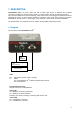
1. DESCRIPTION ePowerSwitch*1GR2 is a power control unit with a built-in Web server, an Ethernet and a RS232 connection. It enables to control the power supply of 1 power outlet1s through an Ethernet connection. This unit offers additional IP device monitoring. It has a Real Time Clock to trigger scheduled actions and timestamp all events. Its serial interface enables to control the power outlet over a Terminal connection (KVM Switch, console server...
RS232 (SUB-D 9F Connector) Serial port RS232 with DB-9 female connector Pinout 2 = TxD 3 = RxD 5 = Gnd The back of the ePowerSwitch 1GR2 Power input 230 VAC – 10 Amp Power outlet Power outlet 230 VAC max 10 Amp 1.2 Package list The following items are included: 5 1 ePowerSwitch 1GR2 1 power cable, 230 V / 10 Amp, length 1.80 Meters 1 RJ45 M/M cable, 2 Meters 1 serial cable SUB-D 9 points M/F, 1.
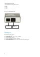
2. INSTALLATION Remark: Make sure that the ePowerSwitch 1GR2 is powered off. Connection instructions 1. Use a shielded RJ45 network cable to connect your ePowerSwitch 1GR2 to the network. 2. Use appropriated three-wire power cords (two poles plus ground) to connect your electrical device to the ePowerSwitch 1GR2 unit. 3. Plug the power cable into a grounded socket. The Status LED lights on to confirm that power is on. 4.
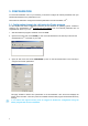
3. CONFIGURATION To use the ePowerSwitch 1GR2 on your network, you must first configure its network parameters. Ask your network administrator for the parameters to use. There are three methods to configure the network parameters of the ePowerSwitch 1GR2: 3.1. Configuration through the LAN using the Finder program It is the simplest and fastest configuration method if you use Windows as operating system.
DHCP: Check this box is you want to obtain the IP address, the subnet mask and the default gateway for your ePowerSwitch 1GR2 via DHCP. Use of DHCP (Dynamic Host Configuration Protocol) requires a DHCP host to be set up on the network. IP Address: IP address of the ePowerSwitch 1GR2, default is 192.168.100.200. Subnet Mask: Subnet Mask of the ePowerSwitch 1GR2, default is 255.255.255.0. Gateway: Generally the address of your router, default is blank.
3.2. Configuration through an RS232 Terminal connection 1. Use the provided RS232 cable to connect the ePowerSwitch 1GR2 to an available serial port of your PC. 2. Run a Terminal program such as Windows HyperTerminal. 3. Configure the appropriate serial port @ 9.600, n, 8, 1 and no flow control. 4. On your computer, press until the menu appears on your screen. 5. Press the “M” on your keyboard and follow the menu to configure the network parameters of your ePowerSwitch 1GR2.
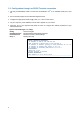
3.3. Configuration through the LAN using a standard Browser During the first installation, change temporarily the network settings of your PC according to the default network settings of the ePowerSwitch 1GR2. Factory network settings of the ePowerSwitch 1GR2: IP Address: 192.168.100.200 - Port: 80 Gateway: 255.255.255.0 1. Open your Web browser and type following IP address: http://192.168.100.200/sysadmin.htm 2. Enter the administrator name and password (default for both = admin) 3.
3.3.1. General / IP configuration This page enables you to define all the IP parameters of the ePowerSwitch 1GR2. DHCP Client enabled: Check this box is you want to obtain the IP address, the subnet mask and the default gateway for your ePowerSwitch 1GR2 via DHCP. Factory default setting for this option is disabled. Use of DHCP (Dynamic Host Configuration Protocol) requires a DHCP host to be set up on the network. IP Address: IP address of the ePowerSwitch 1GR2, default is 192.168.100.200.
3.3.2. General / System time The system time of the ePowerSwitch 1GR2 is used for synchronizing scheduling actions and to timestamp SNMP traps, Syslog information and internal logs. The system time can be set manually with the browser time of the connected computer or can be automatically synchronized with one or two NTP timeservers. Current System Time: This field shows the current system time of the ePowerSwitch 1GR2.
3.3.3. General / SNMP The ePowerSwitch 1GR2 provides a built-in SNMP (Simple Network Management Protocol) agent, which enables you to manage the ePowerSwitch 1GR2 through SNMP-based network management systems. The ePowerSwitch 1GR2 MIB file enables to remotely read out the status of all power outlets and the values of all sensors (temperature, humidity, ambient light). It also enables to control individually all power outlets and all groups of power outlets.
3.3.4. General / Tools This page enables you to: - download and save the current settings of your ePowerSwitch 1GR2 on your PC, - upload an existing configuration file to your ePowerSwitch 1GR2, - restore the factory settings, - download the ePowerSwitch 1GR2 MIB file on your PC. Save: Click this button to save the current system settings onto your local hard drive. Load: Click this button and select a settings file you want to download to the ePowerSwitch 1GR2.
3.3.5. Settings / Accounts 3.3.5.1 Settings / Accounts This page is used to create, activate, deactivate, modify and delete up to 40 accounts. - To activate or deactivate an account, check or uncheck the corresponding checkbox. - To modify an account, click on "Edit" next to the corresponding account. - To delete an existing account, click on "Delete" next to the corresponding account. - To create an account, click on "Add a New Account" on the right side of the page.
Device: In this drop-down list, choose a device from which you want to add Inputs or Outputs to the current account. Inputs/Outputs: This field is used to add/remove Inputs or Outputs to/from the current account. To add Inputs or Outputs to the current account, press the Ctrl key and click on the Inputs/Outputs of the device selected in the previous field. The selected Inputs/Outputs are marked dark blue and their IDs are listed at the right side of the Input/Output field.
3.3.5.2 Settings / Accounts / Hidden Page account This account is intended for developers who want to implement the power outlet control in own programs. If activated, they can access to a special page named hidden.htm and control individually the power outlets using simple commands. - To activate or deactivate this account, check or uncheck the corresponding checkbox. - To modify the Hidden page account, click on "Edit" next to the corresponding account.
Device In this drop-down list, choose the device from which one you want to add an Inputs to the current account. - Only properly connected devices or devices which already have been connected to the Power Switch appears in this field. - Each peripheral is clearly identified by its own ID followed by the name given during the configuration.
3.3.6. Settings / Groups N/A 3.3.7. Settings / Peripherals N/A 3.3.8. Settings / Rules Rules are used to control actions according to a specific event. For example, you can define rules to switch the power outlet OFF from Friday evening to Monday morning. - To remove an existing rule, click on "Delete" of the corresponding rule. - To modify a rule, click on "Edit" of the corresponding rule. This page is used to create, modify and delete rules.
A total of 32 rules can be created and there are 4 different types of rules: 1. Schedule Rule: This rule is used to trigger user-specified actions according to a defined time table. This rule can be used to: - execute once defined actions at specified time and weekday(s). In this case you must only specify the start time and the weekday(s), - execute repeatedly defined actions during a given time.
3.3.8.1. Settings / Rules - Schedule Rule This rule can be used to trigger user-specified actions according to a defined time table. The schedule rule is weekday based and the administrator can declare, for each weekday, a start time, an end time and after what time the rule should be repeated. Activated This check box must be checked to activate the Rule and enables to deactivate temporarily a rule while keeping all its settings for a later use.
Stop Time Defines what time the rule ends. - End Time must be greater than or equal to Start Time. - If the rule has to be executed only once at the selected weekday, enter the same value for Start Time and End Time. - If the rule has to be executed 24 hours at the selected weekday, Start Time must be 1 minute later than EndTime. Applicable weekday Defines which day(s) the rule has to be executed.
3.3.8.2. Settings / Rules - Timer Rule This rule can be used to trigger some actions according to a defined time table. For instance, you could create a rule to switch OFF a Power Outlet every Friday at 6 PM and create another rule to switch the Power Outlets ON again every Monday at 8 AM. Activated This check box must be checked to activate the rule. It enables to deactivate temporarily a rule while keeping all its settings for a later use.
Set Power Outlet: Check this box and in the corresponding drop-down list, choose the power outlet the rule will apply to. In the next corresponding drop-down list, choose the action to execute. Each power outlet can be switched On/Off and restarted. If you choose "restart" you will also be able to define a restart delay between 0 and 65535 seconds. - If you choose 0 second, the delay will be the delay defined in the ePowerSwitch power outlets settings.
3.3.8.3. Settings / Rules - Ping Monitoring Rule This rule can be used to check if a computer or any IP device is connected to the network. It sends ping packets and listens for replies from the specific host. If the host doesn't reply, the ePowerSwitch 1GR2 can automatically switch the powered device off and after a specified delay, switch it again on (for details see Ping & Scan Method).
Delay before First Request after Action: In this field, define the time in seconds before restarting the monitoring after the reboot action. The delay can be set between 30 and 65535 seconds. Maximum Number of Actions In this field, define the maximum number of actions. The number can be set between 0 and 255.
3.3.8.4. Settings / Rules - Scan Monitoring Rule This rule can be used to check if a specific protocol is available on a server (for example HTTP, FTP, Telnet, POP...). If the connection is possible, ePowerSwitch 1GR2 knows that a server program is running there. If the connection is not possible, ePowerSwitch 1GR2 can automatically switch the powered device off and, after a specified delay, switch it again on (for details see Ping & Scan Method).
Number of unsuccessful Requests before Action: In this field, define the number of Port scanning commands to be sent to the IP device before executing the actions. The number can be set between 1 and 65535 seconds. Delay before First Request after Action: In this field, define the time in seconds before restarting the monitoring after the reboot action. The delay can be set between 30 and 65535 seconds. Maximum Number of Actions In this field, define the maximum number of actions.
3.3.9. Settings / Shutdowns This power switch supports shutdown facilities of 1 server via its Serial RS232 interface. - To remove an existing Shutdown association, click on "Delete" of the corresponding rule. - To modify a Shutdown rule, click on "Edit" of the corresponding rule. This page is used to create, modify and delete a Shutdown Association. Click on "Add a New Shutdown" on the right side of the page. A new page appears, allowing you to set all the parameters of the rule.
Shutdown Outputs In this field, choose the output which will be used to trigger the Shutdown. - To select an output, select the output you want to add in the left field and click on the Arrow button, the output will then appear in the right field. - To remove the selected output, select this output in the right field and click on the Arrow button, the output will then appear in the left field.
3.3.10. Misc / Control Panel This page is very helpful for the administrator because it gives a complete overview. At a glance, the administrator can check the status of the power outlet.
3.3.11. Misc / Rule Panel This page shows all the rules the administrator has created and activated. The rules which have been executed can also be highlighted in different colours according to the emergency of the action. The highlight colours can be customized during the creation of the rule (Settings/Rules Page). For supervision purpose, the administrator can create special accounts which display only some specific rules.
3.3.12. Misc / Log The log file keeps a running log of events and activities occurring on the device. The logs are automatically cleared when the device is rebooted. The file will display 10 recent logs.
3.3.13. Misc / Log Settings This page allows you to configure the logs. The Log file is used by the system to record actions, warnings, errors and problems. It is often quite useful to discover the causes of tricky problems. The messages recorded in the log file and sent as copy to a Syslog server are classified into 8 severity levels (Emergency, Alert, Critical, Error, Warning, Notice, Informational and Debug).
4. POWER OUTLET CONTROL 4.1. via the Internet using a standard browser 1. Start your Web browser and type the IP address of your ePowerSwitch 1GR2. The browser displays the authentication dialog box. 2. Enter a user name and its corresponding password. The status of the ePowerSwitch 1GR2 is displayed. 3. In the drop-down list, choose the power control unit you want to control or the rule for which you want to know the status. The ON button allows you to switch ON the power outlet.
4.1. through the network using simple commands in your own program Developers who want to implement the power outlet control in own programs can access to a special page named hidden.htm and control individually the power outlets using simple commands. To configure the Hidden Page Account, go to Settings / Accounts. - To activate or deactivate this account, check or uncheck the corresponding checkbox. - To modify the Hidden page account, click on "Edit" next to the corresponding account.
Device In this drop-down list, choose the device from which one you want to add Inputs or Outputs to the current account. - Only properly connected devices or devices which already have been connected to the Power Switch appears in this field. - Each peripheral is clearly identified by its own ID followed by the name given during the configuration.
The first command must be preceded by a "?" Commands can be concatenated using the character "&" Commands can be specified in upper case, lower case or mixed case Example: if you want to switch to OFF the Power Outlet #1, type in: http://192.168.100.201/hidden.htm?M0:O1=OFF Your Web browser will now display: Hidden Page 21 Dec 2010 02:42:08 Version: 2.1.0.
5. APPENDIX 5.1. Ping and Scan Methods ePowerSwitch 1GR2 has two methods to check whether an IP equipment (PC, server, router, Webcam...) is still alive: Address Pinging: The first method uses the well-known Ping command whereby a request is sent to a specific IP address. The Ping command, which is an echo request, enables you to determine through an ICMP protocol (Internet Control Message Protocol) if an IP device is available on the network.
5.2. Technical Data Network standards: IEEE 802.3, 10 / 100 BASE-T Network protocols: TCP/IP, HTTP Network connection: RJ-45 connector for STP CAT5 Max. network cable length 100 meters Serial connection: RS232, SUB-D 9 female Operating temperature: 0°C to +40°C Operating humidity: 10% to 80% RH (not condensing) Dimensions (LxDxH): 185 x 103 x 43 mm Weight: 1 kg Approvals: CE, EN 60950-1, EN 55022, EN 55024 5.3.
5.4. Syslog Messages: Severity Level Definitions The Emergency level is the most severe type of message generated by ePowerSwitch 1GR2 and the Debug severity level is the least severe one.
STATEMENT OF CONFORMITY STATEMENT OF CONFORMITY NEOL S.A.S. declares that this equipment is in compliance with the Electromagnetic Compatibility Directive 89/336/EEC and the Low Voltage Directive 73/23/EEC Application of Council Directive: 2004/108/EEC Standards to Which Conformity declared: EN 60950-1, EN 55022, EN 55024 Manufacturer's Name and Address: NEOL S.A.