User’s Manual An Intel Soc ket 478 Pr ocessor Based Sock Processor Mainboard (400/533MHz) Suppor ts PC800/ PC 1066 (RIMM3200/RIMM4200) Supports PC800/PC PC1066 RDRAM Memor y Modules Memory TRADEMARK All products and company names are trademarks or registered trademarks of their respective holders. These specifications are subject to change without notice. $ ")7 Manual Revision 1.
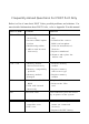
Frequently Asked Questions For POST Port Only Below is a list of some basic POST Codes, possible problems, and solutions. For more detailed information about POST Codes, refer to Appendix E in this manual. P O ST C O D E P r o bl e m So l uti o n FFh o r CFh 1 .B IO S c hip inse rte d 1 . Re inse rt the B IO S inc o rre c tly 2 . Inc o rre c t BIO S update ve rsio n c hip 2 . D o wnlo ad the c o rre c t BIO S ve rsio n update 3 . M ainbo ard pro ble m fro m the m anufac ture r's 4 .
Table of Contents Page Section 1 Introduction Components Checklist .............................................. 1-1 Overview System Overview ....................................................... 1-2 Chipset Components ................................................. 1-3 Intel Pentium 4 Processors ...................................... 1-4 Direct Rambus ........................................................... 1-5 Bandiwdth Overview ..................................................
Section 4 Award BIOS Setup Main Menu ................................................................ 4-1 Standard CMOS Setup ............................................... 4-2 Advanced BIOS Features ........................................... 4-3 Advanced Chipset Features ....................................... 4- 8 Integrated Peripherals ............................................... 4-10 Power Management Setup ........................................ 4-15 PNP/PCI Configuration Setup ..................
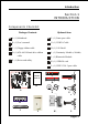
Introduction Section 1 INTRODUCTION Components Checklist Package Contents Optional Item A. (1) Mainboard F. (1) Game port cable B. (1) Users manual G. (1) USB2.0 Cable C. (1) Floppy ribbon cable H. (1) I/O Shield D. (1) ATA-66/100 hard drive ribbon I. (1) Continuity Module (C-RIMM) cable J. (1) Bluetooth Module E. (1) Driver and utility K. (1) SPD650 card L.
Introduction System Overview This board is designed with Intel® 850E chipset. The Intel® 850E chipset includes MCH(FW82850E), ICH4(FW82801DB) and FWH three chips. The Intel® 850E chipset designed for Intels FC-PGA2 socket 478 package architecture and support the 4X capability of the AGP 2.0 Interface Specification and 400/ 533MHz Direct RDRAM. The 400/533MHz, 32bit, double clocked Direct RDRAM interface provides 3.2/4.2GB/s access to main memory.
Introduction Chipset Components The Intel® 850E chipset consists of the Memory Controller Hub (MCH), the I/O Controller Hub (ICH4) and the Firmware Hub (FWH). ! Memory Controller Hub (MCH) The MCH provides the interconnect between the Direct RDRAM and the system logic. It integrates: - Support for single processor with a data transfer rate of 400/533MHz. - 400/533MHz Direct RDRAM interface supporting 2GB of Direct RDRAM. - 2X, 4X, 1.5V AGP interface (Only support 1.5V on AGP interface).
Introduction Intel Pentium 4 processors Formally known as the Willamette, the PentiumTM 4 is the next generation IA-32 processor from Intel. This next generation design is based upon a new microarchitecture that brings higher clock speeds and performance than previous processors could deliver. Among other advanced features the Pentium 4 offers Streaming SIMD extensions 2, Advanced Dynamic Execution, Hyper Pipelined Technology, and a data transfer rate of 400/533MHz system bus.
Introduction Pentium 4 also introduces a 400/533MHz system bus as opposed to the 100 and 133MHz bus seen in previous Pentium III processors. This allows 3.2Gbytes per second of throughput while the Pentium III had a limited 1.06Gbyte/s throughput. Willamette will reportedly be introduced in the 0.18-micron using aluminum. For more information about all the cool new features the Pentium 4 delivers check out the Intel website at http://www.intel.
Introduction Bandwidth Overview Table 1 provides a summary of the bandwidth requirements for the Intel® 850E chipset. Interface Clock Speed (MHz) Samples Per Clock (Mega-samples/s) Data Rate Data Width (Bytes) Bandwidth (MB/s) CPU Bus 100/133 4 400/533 8 3200/4264 RDRAM 400/533 2 800/1066 4 3200/4264 AGP 2.0 66.6 4 266 4 1066 Hub Link 66.6 4 266 1 266 PCI 2.2 33.3 1 33.3 4 133 Table 1: Intel® 850E platform Bandwidth Summary Accelerated Graphics Port (AGP or A.G.P.
Introduction Ultra ATA/66/100 The board provides an Ultra ATA/66/100 Bus Master IDE controller. This controller supports Ultra ATA/66/100 protocols which are ideal for supporting demanding applications such as real-time video, multimedia, and a high performance operating system. A new IDE cable is required for Ultra ATA/66/100. This cable is an 80-pin conductor cable, which is backwards compatible with ATA/33 connectors.
Introduction Mainboard Form-Factor The board is designed with an ATX form factor. The ATX form factor is essentially a Baby-AT baseboard rotated 90 degrees within the chassis enclosure and a new mounting configuration for the power supply. With these changes the processor is relocated away from the expansion slots, allowing them to hold full length add-in cards.
Introduction I/O Shield Connector The board is equipped with an I/O back panel (Figure 3). Ensure that your computer case has the appropriate I/O cutout. Parallel Port RJ-45 LAN PS/2 Mouse MIC-in Line-in Line-out PS/2 Keyboard USB2.0 ports COM1 COM2 USB2.0 ports Figure 3: I/O ports Power-On/Off (Remote) The board has a single 20-pin connector for ATX power supplies (Figure 4).
Introduction System Block Diagram Pentium 4 Processor 478 pin Package 133/100MHz 4X (1.
.A=JKHAI Section 2 FEATURES Mainboard Features ! PROCESSOR ® ® - Socket 478 Intel Pentium 4 processor from 1.4 to 2.4GHz ! CHIPSET - Intel 82850E Chipset (82850E + ICH4) ! FRONT SIDE BUS - 400/533MHz ! DRAM MODULE - 232-pin RIMM x 2 (32-bit) for PC800/PC1066 (RIMM3200/RIMM4200) RDRAM - DRAM Size: 128MB to 2GB (2 channel max. 32 Devices) ! EXPANSION SLOT - 32-bit PCI x 5 - 4: AGP x 1 (1.
.A=JKHAI - PCI Bus IDE Port with PIO/Ultra DMA-66/100 x 2 (up to 4 devices) - Extra IDE Port by HPT372 with Ultra DMA-100/133 and IDE RAID x 2 (up to 4 devices) * Supports JBOD function (Just a Bunch of Disks). JBOD are a group of hard disks in a computer that are not configured in a RAID.
.A=JKHAI ! EXTENDED FUNCTION - Supports hardware monitoring function by W83627HF-AW - Supports exclusive KBPO (Keyboard Power On) function - Supports Wake-On-LAN function - Supports STR (Suspend To RAM) power saving function - Supports CPU clock and ratio settings via BIOS - Supports CPU Vcore and memory, and AGP voltage settings via BIOS - Supports Asynchronous Transfer Mode between PCI & FSB - Supports Magic Health and Easy Boot Function - Supports AGP card 1.
.A=JKHAI Page Left Blank Page 2-4
Installation Section 3 INSTALLATION Page 3-1
Installation Mainboard Layout Page 3-2
Installation Easy Installation Procedure The following must be completed before powering on your new system: 3-1. CPU Installation 3-2. Jumper Settings 3-3. System memory Configuration 3-4. Device Connectors 3-5. STR Function 3-6. 850E platform AGP Card 3.3V Protection Section 3-1 CPU Installation Figure 2 Figure 1 Pin 1 Step 1 Step 2 Open the socket by raising the actuation lever. Align pin 1 on the CPU with pin 1 on the CPU socket as shown in the illustration above.
Installation Figure 3 Figure 4 Step 3 Step 4 Close the socket by lowering and locking the actuation lever. Apply thermal compound to the top of the CPU and install the heatsink as shown. Figure 5 Figure 6 Step 5 Step 6 Install the cooling fan assembly. Press the two clips in the direction of the arrows shown in Figure 5 to secure the assembly to the CPU socket. Plug the CPU fan into the CPU fan connector (FAN1). The installation is complete.
Installation Section 3-2 Jumper Settings JCMOS1 CMOS Clear 1-2 Normal (Default) 2-3 Clear CMOS Page 3-5
Installation Section 3-3 System RIMM Memory Module Configuration Memory Layout The board supports two channels (2) 232-pin RIMMs (Rambus Interface Memory Module) as shown in Figure 7. The RIMMs can be RIMM and C-RIMM (Continuity RIMM) only. RIMM modules have Rambus channel signals as their memory interface. A RIMM module may contain up to a maximum of 16 RDRAM devices. All RDRAM devices on a RIMM must have the same timing characteristics.
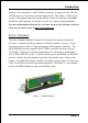
Installation The figure 8 below shows the RSL interconnections between 850E (MCH) and two RDRAM channel. This figure describes the logical interconnections, and is not a physical representation of RDARM devices on a motherboard.
Installation The table 1 below shows the onboard RIMM memory socket population. RIMM Socket# of Onboard System Accept Max. of RDRAM devices on a Channel Total Memory RIMM1 RIMM2 Status Device Size RIMM RIMM OK 16 x 2 2048MB (2GB) * RIMM C-RIMM OK 16 1024MB (1GB) * C-RIMM RIMM OK 16 1024MB (1GB) * Any RIMM socket is empty or the RIMM Module is not properly inserted. Failure, System can't boot and no display. Table 1: Onboard RIMM memory socket population.
Installation RIMM/C-RIMM Module Installation This section describes some basic RIMM/C-RIMM installations as described in table 1. Note that continuity Modules are required in empty sockets. Figure 9, 10 and 11 display common installations. RIMM or RDRAM signals are daisychained through each device on RIMM and memory module.
Installation Figure 12 displays the notch marks and what they should look like on your RIMM memory module. RIMMs have 232-pins and one notch that will match with the onboard RIMM socket. RIMM modules are installed by placing the chip firmly into the socket at a 90 degree angle and pressing straight down (figure 13) until it fits tightly into the RIMM socket (figure 14).
Installation Figure 12a displays the notch marks and what they should look like on your C-RIMM memory module. C-RIMMs have 232-pins and one notch that will match with the onboard C-RIMM socket. C-RIMM modules are installed by placing the chip firmly into the socket at a 90 degree angle and pressing straight down (figure 13a) until it fits tightly into the RIMM socket (figure 14a).
Installation Section 3-4 Device Connectors Parallel Port RJ45 LAN PS/2 Mouse MIC Line_in Speaker PS/2 Keyboard USB 2.0 port COM1 COM2 USB 2.0 port Figure 15: I/O ports JFAN1 / JFAN2 / JFAN3: The plug-in for CPU/Power/Chassis Fan power JFAN2: Power Fan JFAN3: Chassis Fan GND +12V NC GND +12V Rotation JFAN1: CPU Fan GND +12V Rotation JFAN1 JFAN2 JFAN3 JWOL:WOL (Wake On LAN) Connector Reserved for NIC (Network Interface Card) to wake the system.
Installation IDE1/2: Ultra DMA-66/100 Primary / Secondary IDE Connector (Blue) UIDE1/2: Ultra DMA-66/100/133 & RAID Primary/Secondary IDE Connector (Red) Supported by HTP372 chipset FDD1: Floppy Controller Connector (Black) PW1: ATX Power Connector (20-pin power connector) PW1 GAME1: Game port connector GAME1 CD_IN: CD Audio_IN Connector CD_IN_Right CD_Reference 1 CD_IN AUX_IN CD_IN_Left AUX_IN: Auxiliary Line_IN Connector CD_IN_Right GND 1 CD_IN_Left Page 3-13
Installation SPDIF: Sony/Philips Digital Interface This connector is the digital link between the mainboard and your audio devices, such as CD player, sampler or DAT recorder. It allows the digital transmission of audio data in SPDIF format. SPDIF_OUT GND NC $ # VCC SPDIF_IN 1394-1 / 1394-2: (Optional ) 400Mbps 1394a (FireWire) Connectors 1394-1 and 1394-2 enable you to connect two IEEE 1394 ports for use with external devices that conform to the IEEE 1394 specification.
Installation USB3: USB port header for two USB2.0 ports. The USB3 is used to connect bluetooth module for wireless connection. VCC GND -Data +Data +Data -Data GND VCC ' USB port header pin descriptions.
Installation " Power On/Off (This is connected to the power button on the case. Using the Soft-Off by Pwr-BTTN feature, you can choose either Instant Off (turns system off immediately), or 4 sec delay (you need to push the button down for 4 seconds before the system turns off). When the system is in 4 sec delay mode, suspend mode is enabled by pushing the button momentarily.) J3 " Turbo LED indicator " IDE LED indicator LED ON when Onboard PCI IDE Hard disks is activate " IR Connector 1. VCC 2. CIRRX 3.
Installation 3-5 STR (Suspend To RAM) Function This mainboard supports the STR (Suspend To RAM) power management scheme by maintaining the appropriate power states in the DDR SDRAM interface signals. The power source to the DDR SDRAM must be kept active during STR (ACPI S3). Advanced Configuration Power Interface (ACPI) provides many Energy Saving Features for operating systems that support Instant ON and QuickStart TM function. 1.
Installation 3-7 850E Platform AGP Card 3.3V Protection The Intel® 850E chipset supports 1.5 volt AGP graphics cards only. Using a 3.3 volt AGP card in an Intel® 850E chipset-based board might damage the chipset on an 845E equipped mainboard. However, this mainboard features a protection function that prevents the system from powering on when a 3.3V AGP card is inadvertently inserted into the AGP slot. If this happens, we recommend you to follow these steps: Step 1: Remove the 3.
BIOS Section 4 AWARD BIOS SETUP Main Menu Awards ROM BIOS provides a built-in Setup program which allows user to modify the basic system configuration and hardware parameters. The modified data is stored in a battery-backed CMOS, so that data will be retained even when the power is turned off. In general, the information saved in the CMOS RAM will stay unchanged unless there is a configuration change in the system, such as hard drive replacement or a device is added.
BIOS The main menu displays all the major selection items. Select the item you need to reconfigure. The selection is made by moving the cursor (press any direction (arrow key ) to the item and pressing the Enter key. An on-line help message is displayed at the bottom of the screen as the cursor is moved to various items which provides a better understanding of each function. When a selection is made, the menu of the selected item will appear so that the user can modify associated configuration parameters.
BIOS Notes: _ If the hard disk Primary Master/Slave and Secondary Master/Slave are set to Auto, then the hard disk size and model will be auto-detected. _ The Halt On: field is used to determine when to halt the system by the BIOS if an error occurs. _ Floppy 3 Mode support is a mode used to support a special 3.5-inch drive used in Japan. This is a 3.5-inch disk that stores 1.2 MB. The default setting for this is disabled.
BIOS Virus Warning During and after system boot up, any attempt to write to the boot sector or partition table of the hard disk drive halts the system and an error message appears. You should then run an anti-virus program to locate the virus. Keep in mind that this feature protects only the boot sector, not the entire hard drive. The default is Disabled. Enabled: Activates automatically when the system boots up causing a warning message to appear when anything attempts to access the boot sector.
BIOS HDD S.M.A.R.T. Capability The S.M.A.R.T. (Self-Monitoring, Analysis, and Reporting Technology) system is a diagnostics technology that monitors and predicts device performance. S.M.A.R.T. Software resides on both the disk drive and the host computer. The disk drive software monitors the internal performance of the motors, media, heads, and electronics of the drive. The host software monitors the overall reliability status of the drive.
BIOS Typematic Rate (Chars/Sec) This is the number of characters that will be repeated by a keyboard press. The default is 6. Options: 6 ~ 30 characters per second. Typematic Delay (msec) This setting controls the time between the first and the second character displayed by typematic auto-repeat. The default is 250. Options: 250/500/750/1000 msec. Security Option This category allows you to limit access to the System and Setup, or just to Setup. The default is Setup.
BIOS First /Second/Third/Other Boot Device The BIOS attempts to load the operating system from the devices in the sequence selected in these items. Options: Floppy, LS120, HDD-0, SCSI, CDROM, HDD-1, HDD-2, HDD-3, ZIP100, USB-FDD, USB-ZIP, USB-CDROM, USB-HDD, LAN, Disabled. Boot Other Device When enabled, the system searches all other possible locations for an operating system if it fails to find one in the devices specified under the first, second, and third boot devices. The default is Enabled.
BIOS 4-3 Advanced Chipset Features Choose the ADVANCED CHIPSET FEATURES option in the CMOS SETUP UTILITY menu to display following menu. Figure 4: Chipset Features Setup DRAM Bus Frequency This item allows you select DRAM Bus Frequency. The Choice: AUTO, 400MHz, 533MHz, 300MHz. DRAM Data Integrity Mode Use this option to configure the type of DRAM in your system. The choice: No-ECC, ECC. System BIOS Cacheable This item allows the system to be cached in memory for faster execution.
BIOS Video RAM Cacheable This option allows the CPU to cache read/writes of the video RAM. Options: Disabled, Enabled. Delayed Transaction The mainboards chipset has an embedded 32-bit post write buffer to support delay transactions cycles. Select Enabled to support compliance with PCI specification version 2.1. The default is Enabled. Options: Disabled, Enabled. AGP Aperture Size (MB) This item defines the size of the aperture if you use an AGP graphics adapter.
BIOS 4-4 Integrated Peripherals Figure 5: Integrated Peripherals Notes: If you do not use the Onboard IDE connector, then you will need to set Onboard Primary PCI IDE: Disabled and Onboard Secondary PCI IDE: Disabled The Onboard PCI IDE cable should be equal to or less than 18 inches (45 cm.). Init Display First If two video cards are used (1 AGP and 1 PCI) this specifies which one will be the primary display adapter. The default is PCI Slot. Options: PCI Slot, AGP.
BIOS Onboard IDE Device Setup Scroll to Onboard IDE Device Setup and press . The following screen appears: On-Chip Primary PCI IDE The integrated peripheral controller contains an IDE interface with support for two IDE channels. Select Enabled (default) to activate each channel separately. Options: Enabled, Disabled.
BIOS Onboard PCI Device Setup Scroll to Onboard PCI Device Setup and press . The following screen appears: USB Controller Enables the all USB controller. Options: Disabled, Enabled. EHCI (USB2.0) Controller Enables the EHCI (USB2.0) controller. Options: Disabled, Enabled. USB Keyboard Support Your system contains a Universal Serial Bus (USB) controller and you have a USB keyboard Device. The default is Auto detect. Options: Enabled, Disabled.
BIOS Midi Port Address Select an address for the Midi port. Options: 290, 300, 330 (default), Disabled. Midi Port IRQ Select an interrupt for the Midi port. Options: 5, 10 (default). Onboard I/O Chip Setup Scroll to Onboard I/O Chip Setup and press . The following screen appears: Onboard FDC Controller Select Enabled if your system has a floppy disk controller (FDC) installed on the system board and you wish to use it.
BIOS IR Transmission delay This item allows you to enabled/disable IR transmission delay. Options: Enabled, Disabled. UR2 Duplex Mode This item allows you to select IR half/full duplex function. Options: Half, Full. Use IR Pins This item allows you to select IR transmission routes, one is RxD2, TxD2 (COM Port) and the other is IR-Rx2Tx2. Options: IR-Rx2Tx2, RxD2, TxD2. Onboard Parallel Port This field allows the user to configure the LPT port. Options: 378/IRQ7, 278/IRQ5, 3BC/IRQ7, Disabled.
BIOS 4-5 Power Management Setup Choose the POWER MANAGEMENT SETUP in the CMOS SETUP UTILITY to display the following screen. This menu allows the user to modify the power management parameters and IRQ signals. In general, these parameters should not be changed unless its absolutely necessary. Figure 6: Power Management ACPI Suspend Type This item allows you to select S1(POS) or S3(STR) function. When set to S3 (STR) or S1&S3 the following two fields become available.
BIOS ACPI Function This item allows you to enable/disable the Advanced Configuration and Power Management (ACPI). Options: Enabled, Disabled. Run VGABIOS if S3 Resume This determines whether or not to enable the system to run the VGA BIOS when resuming from S3(STR) or S1&S3. Options: Auto, Yes, No. Power Management Use this to select your Power Management selection. The default is User define. Max. saving: Maximum power savings. Inactivity period is 1 minute in each mode. Min. saving: Minimum power savings.
BIOS MODEM Use IRQ Name the interrupt request (IRQ) line assigned to the modem (if any) on your system. Activity of the selected IRQ always awakens the system. Default is IRQ 3. Options: N/A, 3, 4, 5, 7, 9, 10, 11 Suspend Mode enabled and after the set time of system inactivity, all devices except the CPU will be shut off. Options: Enabled, Disabled. HDD Power Down When enabled and after the set time of system inactivity, the hard disk drive will be powered down while all other devices remain active.
BIOS CPU THRM-Throttling Select the CPU THRM-Throttling rate. Options: 12.5%, 25.0%, 37.5%, 50.0%, 62.5%, 75.0%, 87.5%. Resume by Alarn When enabled, you can set the date and time in the following two fields. Any event occurring at the specified date or time awakens the system from power savings mode. POWER ON Function Enables computer power on by keyboard, mouse, or hotkey activity. The default is Hot KEY. Password: Requires you to enter a password when using the keyboard to power on.
BIOS PWRON After PWR-Fail This item enables your computer to automatically restart or return to its last operating status after power returns from a power failure. Off: The system stays off after a power failure. Former-Sts: The system returns to the state it was in just prior to the power failure. ** Reload Global Timer Events ** Primary/Secondary IDE 0/1 Any activity occuring on these channels awakens the system from power savings mode.
BIOS 4-6 PNP/PCI Configuration The PNP/PCI configuration program is for the user to modify the PCI/ISA IRQ signals when various PCI/ISA cards are inserted in the PCI or ISA slots. WARNING: Conflicting IRQs may cause the system to not find certain devices. Figure 7: PNP/PCI Configuration Setup Reset Configuration Data This setting allows you to clear ESCD data. The default is Disabled Disabled:Normal Setting.
BIOS PCI/VGA Palette Snoop This item is designed to overcome problems that can be caused by some nonstandard VGA cards. This board includes a built-in VGA system that does not require palette snooping so you must leave this item disabled. Options: Enabled, Disabled. PCI Latency Timer (CLK) The latency timer defines the minimum amount of time, in PCI clock cycles, that the bus master can retain the ownership of the bus. Options: 0-255.
BIOS Interrupt requests are shared as shown below: INT A AGP Slot INT B INT C INT D AC97/MC97 V Slot 4 V Slot 5 V Onboard LAN V V V Onboard USB3 V USB 2.0 V V HighPoint IMPORTANT! If using PCI cards on shared slots, make sure that the drivers support Shared IRQ or that the cards dont need IRQ assignments. Conflicts will arise between the two PCI groups that will make the system unstable or cards inoperable.
BIOS 4-7 PC Health Status 33oC/91oF 59oC/138oF 0 RPM 0 RPM 0 RPM 1.50V 1.75V 2.50V 4.97V 12.12V -12.28V -5.09V 3.48V 4.89V Figure 8: PC Health Status Show PC Health in POST When this function is enabled the PC Health information is displayed during the POST (Power On Self Test). CPU Warning Temperature Sets the temperature at which the computer will respond to an overheating CPU. The default is Disabled. Options: Disabled, 50OC/122OF ~ 70OC/158OF.
BIOS Vcore (V) The voltage level of the CPU(Vcore). 2.50 (V) The voltage level of the RDRAM. ± 5V, ± 12V, VBAT(V), 5VSB(V) The voltage level of the switching power supply. ACPI Shutdown Temperature This is the temperature that the computer will turn off the power to combat the effects of an overheating system. (requires ACPI to be enabled in Power Management BIOS and ACPI compliant operating system.) The default is Disabled. Options available are 60oC/140oF to 75oC/167oF in increments of 5oC.
BIOS 4-8 Frequency/Voltage Control 1.75V 1.75V 1.50V 1.50V 2 . 50V 2 . 50V Figure 9: Frequency/Voltage Control CPU Clock Ratio Use this item to select a multiplier for the system frontside bus (FSB) frequency. The value of the multiplier must be set so that: Multiplier x Frontside Bus Frequency = CPU Clock Speed For example, if you have a processor that is rated to run at 450 MHz and the system is running a frontside bus frequency of 100 MHz, you should select a multiplier of 4.5 so that: 4.
BIOS Spread Spectrum Modulated If you enable spread spectrum, it can significantly reduce the EMI (ElectroMagnetic Interference) generated by the system. AGP/PCI Clock Enables you to set the host clock to work concurrently with the PCI bus and the AGP bus. The default is AUTO, if FSB > 109MHz then AGP/PCI fixed to 66MHz/ 33MHz. When the FSB is 133MHz, the options will display Auto, AGP-FSB*2/4 PCIFSB/4, AGP-66MHz PCI-33MHz.
BIOS DIMM Voltage This item allows you to set the DIMM slot voltage. The default is +0.00V. Options: +0.00V to +0.70V in 0.10V increments. We recommend that you leave this at the default value.
BIOS 4-10 Supervisor/User Password Setting These items are used to install a password. A Supervisor password takes precedence over a User password, and the Supervisor limits the activities of a User. You can set either a supervisor or user password, or both of them: Supervisor password: authorized to enter and change the options of the setup menus. User password: authorized to enter, but not authorized to change the options of the setup menus.
BIOS 4-11 Exiting BIOS Save & Exit Setup Pressing on this item asks for confirmation: Save to CMOS and EXIT (Y/N)? Y Pressing Y stores the selections made in the menus in CMOS a special section of memory that stays on after you turn your system off. The next time you boot your computer, the BIOS configures your system according to the Setup selections stored in CMOS. After saving the values the system is restarted again.
BIOS Page Left Blank Page 4-30
Drivers Installation Section 5 Driver Installation Easy Driver Installation INTEL 850E+ICH4 CHIPSET DRIVER INTEL CHIPSET INF FILES INTEL APPLICATION ACCELERATOR AC97 AUDIO DRIVER HPT 370(A)/372 PLEASE INSTALL THE DRIVER FROM 3.5 FLOPPY RAID ADMINISTRATOR VIA REALTEK LAN DRIVER INTEL ICH4 USB2.0 DRIVER ACROBAT READER CD EXPLORER EXIT Insert the bundled CD-disk. Step 1 : Click INTEL CHIPSET INF FILES. Install all components recommended. Step 2 : Click INTEL APPLICATION ACCELERATOR.
Drivers Installation ALC650 Configuration Setup (6 Channel) ! To enable ALC650 Function 1. Right-click Sound Effect button in the tool bar display currently selected Titles. Select Sound Manager. Sound Effect: 2. Click Sound Effect button and select Environment from the drop-down menu.
Drivers Installation Equalizer: 3. Click Equalizer and setup the value of dB. Speak Configutation: 4. Click Line in and Mic in buttons to enable 6 channel function as this is required for the ALC650.
Drivers Installation Speak Configutation: 5. The selected screen appears. Speaker Test: 6. Click Speaker Test button and click on the speakers directly which show on the screen to test it.
Drivers Installation General: 7. General Information for user reference.
Drivers Installation Page Left Blank Page 5-6
Appendix Appendix A A-1 Avance® Media Player User’s Guide Avance® Media Player Platform J B 3 1 4 A 7 8 5 2 C 6 D I E F G H Functional Descriptions A. Playback Windows Display Playback windows displays the following mode information: 1. Playback Time Display 2. Voice Cancellation Mode Display 3. Pitch Mode Display 4. Surround Sound Mode Display B. Playback Function Controls There are 8 selectable functions for the playback: 1. Volume control High/Low Adjustment Bar. 2.
Appendix 3. Repeat mode Choice of Repeat, All Repeat, Random or No Repeat Mode. 4. Mute Mute On/Off Mode select. 5. Voice cancellation Voice Cancellation On/Off Mode select for Karaoke. 6. Surround mode A total of 26 Surround Sound mode select as shown in the table below.
Appendix F. Title/Play List Edit Controls There title/play list controls include “Add”, “Del”, “Clear”, “Load”, & “Store”. 1. Add Add to the Title/Play List. 2. Del Remove form the Title/Play List. 3. Clear Clear the Title/Play Lost. 4. Load Load Title/Play List. 5. Store Save Title/Play List. G. Title/Play List Scroll bar Scroll Up/Down the Title/Play List. H. Recording Function Controls The recording function controls include “Input”, “Save:, “New”, “Rec”, “Stop”, & “Play”. 1.
Appendix Page Left Blank A-4
Appendix Appendix B B-1 Update Your System BIOS Download the xxxxx.EXE file corresponding to your model form the our website to an empty directory on your hard disk or floppy. Run the downloaded xxxxx.EXE file and it will self extract. Copy these extracted files to a bootable DOS floppy disk. Note: The DOS floppy disk should contain NO device drivers or other programs. 1. Type “A:\AWDFLASH and press Key. 2. You will see the following setup on screen. 3. Please key in the xxxxx.bin BIOS file name.
Appendix 5. Key in File Name to save previous BIOS to file. XXXX XXXXX xxxxx.bin xxxxx.bin 6. Are you sure to program (y/n), please key in [Y] to start the programming. XXXX XXXXX xxxxx.bin xxxxx.bin 7. The programming is finished. XXXX XXXXX xxxxx.
Appendix Appendix C C-1 EEPROM BIOS Remover Do not remove the BIOS chip, unless instructed by a technician and only with a PLCC IC extractor tool. The BIOS socket may be damaged if using an improper method to replace the BIOS chip.
Appendix Page Left Blank C-2
Appendix Appendix D D-1 GHOST 7 Quick User’s Guide (Optional) Installation is very easy. You only need to copy the Ghost7 folder or Ghost.exe to your hard disk. Main Menu Description of Menu Ghost clones and backs up Disk and Partition.
Appendix Disk There are 3 hard disk functions: 1. Disk To Disk (disk cloning) 2. Disk To Image (disk backup) 3. Disk From Image (restore backup) Important! 1. To use this function, the system must have at least 2 disks. Press the Tab key to move the cursor. 2. When restoring to a destination disk, all data in that disk will be completely destroyed. Disk To Disk (Disk Cloning) 1. Select the location of the Source drive. 2. Select the location of the Destination drive.
Appendix 3. When cloning a disk or restoring the backup, set the required partition size as shown in the following figure. 4. Click OK to display the following confirmation screen. Select Yes to start. Disk To Image (Disk Backup) 1. Select the location of the Source drive.
Appendix 2. Select the location for storing the backup file. 3. Click OK to display the following confirmation screen. Select Yes to start. Disk From Image (Restore Backup) 1. Select the Restoring file.
Appendix 2. Select the Destination drive of the disk to be restored. 3. When restoring disk backup, set the required partition size as shown in the following figure. 4. Click OK to display the following confirmation screen. Select Yes to start.
Appendix Partition There are 3 partition functions: 1. Partition To Partition (partition cloning) 2. Partition To Image (partition backup) 3. Partition From Image (restore partition) Partition To Partition (Partition Cloning) The basic unit for partition cloning is a partition. Refer to disk cloning for the operating method. Partition To Image (Partition Backup) 1. Select the disk to be backed up.
Appendix 2. Select the first partition to be backed up. This is usually where the operating system and programs are stored. 3. Select the path and file name to store the backup file. 4. Is the file compressed? There are 3 options: (1) No: do not compress data during backup (2) Fast: Small volume compression (3) High: high ratio compression. File can be compressed to its minimum, but requiring longer execution time.
Appendix 5. Select Yes to start performing backup. Partition From Image (Restore Partition) 1. Select the backup file to be restored. 2. Select the source partition.
Appendix 3. Select the disk to be restored. 4. Select the partition to be restored. 5. Select Yes to start restoring. Check This function is to check possible error caused by defective FAT or track during backup or restoring.
Appendix How to Reinstall Windows in 2 Minutes This chapter guides you how to setup your computer properly and, if necessary, reinstall Windows in 2 minutes. Ghost provides different methods to complete this task. The following two sections explain how to create an emergency Recover Floppy and Recover CD: Emergency Recover Floppy Divide a hard disk into two partitions. The first partition is to store the operating system and application programs.
Appendix (2) After booting, the screen displays the Menu. Select Backup or Restore: Since the user may install other applications in the future, he/she may alter Autoexec.bat file to back up or restore the user-defined Image file as follows: # Backup Back up Windows and application programs as a file (Recent. gho). Command is: Ghost clone,mode=pdump,src=1:1,dst=d:\Recent.gho -fx sure -rb # Restore Restore types include [General Windows] and [Windows and Application Programs].
Appendix Recover CD The following is a simple guide to create a recover CD: 1. First, create a recover floppy disk contains the following with any copy program such as Easy CD Create (Note 2) : Bootable files (Command.com and Io.sys and MSDOS.SYS) Config.sys (Configuration setup file) Autoexec.bat (Auto-execution batch file) Mscdex.exe (CD-Rom execution file) Ghost.exe (Ghost execution file) Oakcdrom.sys (ATAPI CD-ROM compatible driver) The content of Config.sys is: DEVICE=Oakcdrom.
Appendix Ghost Command Line Switches Reference Ghost may be executed in interactive or in batch mode. Most of the Ghost switches are used to assist in batch mode operation. To list switches, type ghost.exe -h. -clone The full syntax for this switch is: clone,MODE={copy|load|dump|pcopy|pload|pdump},SRC= {drive|file|drive:partition|,DST={drive|file|drive:partition},SZE{F|L|n= {nnnnM|nnP|F|V}} Clone using arguments.
Appendix c) DST Mode COPY/ LOAD DUMP PCOPY/ PLOAD PDUMP d) SZEy This defines the destination location for the operation: Meaning Destination drive (e.g, 2 for drive two) Disk image filename or device,(e.g, g:\images\system2.img) Destination partition,(e.g, 2:2 indicates the second partition on drive two). Partition image filename (e.g, g:\images\part1.img). Partition size to be transferred. Available Options: F Resizes the first partition to maximum size allowed based on file system type.
Appendix destination partitions in proportion to the data usage in the source partitions Someexamples follow that will help illustrate: -fx flag Exit. Normally when Ghost has finished copying a new system to a disk, it prompts the user to reboot with a press Ctrl-Alt-Del to reboot window. However, if Ghost is being run as part of a batch file it is sometimes useful to have it just exist back to the DOS prompt after completion so that further batch commands may be processed. -fx enables this.
Appendix Example 1: To copy drive one to drive two on a PC, without final prompt if OK to proceed. ghost.exe -clone,mode=copy,src=1,dst=2 sure Example 2: To connect via NetBIOS to another PC running Ghost in slave mode, and dump a disk image of local drive two to the remote file c:\drive2.gho ghost.exe -clone,mode=dump,src=2,dst=C:\drive2.gho -nbm Note: The slave Ghost can start with ghost nbs command Example 3: To copy drive one of second partition from a PC to drive two of first of the same PC, ghost.
Appendix Appendix E E-1 POST CODES (Optional) POST (hex) DESCRIPTION CFh C0h Test CMOS R/W functionality. Early chipset initialization: - Disable shadow RAM - Disable L2 cache (socket 7 or below) - Program basic chipset registers Detect memory - Auto-detection of DRAM size, type and ECC. - Auto-detection of L2 cache (socket 7 or below) Expand compressed BIOS code to DRAM Call chipset hook to copy BIOS back to E000 & F000 shadow RAM.
Appendix 0Eh 0Fh 10h 11h 12h 13h 14h 15h 16h 17h 18h 19-1Ah 1Bh 1Ch 1Dh 1Eh 1Fh 20h 21h 22h 23h E-2 Test F000h segment shadow to see whether it is R/W-able or not. If test fails, keep beeping the speaker. Reserved Auto detect flash type to load appropriate flash R/W codes into the run time area in F000 for ESCD & DMI support. Reserved Use walking 1s algorithm to check out interface in CMOS circuitry. Also set real-time clock power status, and then check for override.
Appendix 4. 24-26h 27h 28h 29h 2A-2Ch 2Dh 2E-32h 33h 34-3Bh 3Ch 3Dh 3Eh 3Fh 40h 41h 42h 43h 44h 45-46h 47h Onboard clock generator initialization. Disable respective clock resource to empty PCI & DIMM slots. 5. Early PCI initialization: -Enumerate PCI bus number -Assign memory & I/O resource -Search for a valid VGA device & VGA BIOS, and put it into C000:0. Reserved Initialize INT 09 buffer Reserved 1. Program CPU internal MTRR (P6 & PII) for 0-640K memory address. 2.
Appendix 48h 49h 4A-4Dh 4Eh 4Fh 50h 51h 52h 53-54h 55h 56h 57h 58h 59h 5Ah 5Bh 5Ch 5Dh 5E-5Fh 60h 61-64h 65h E-4 Reserved 1. Calculate total memory by testing the last double word of each 64K page. 2. Program writes allocation for AMD K5 CPU. Reserved 1. Program MTRR of M1 CPU 2. Initialize L2 cache for P6 class CPU & program CPU with proper cacheable range. 3. Initialize the APIC for P6 class CPU. 4.
Appendix 66h 67h 68h 69h 6Ah 6Bh 6Ch 6Dh 6Eh 6Fh 70-72h 73h 74h 75h 76h 77h 78h 79h 7Ah 7B-7Eh 7Fh 80h 81h 82h Reserved Prepare memory size information for function call: INT 15h ax=E820h Reserved Turn on L2 cache Reserved Program chipset registers according to items described in Setup & Auto-configuration table. Reserved 1. Assign resources to all ISA PnP devices. 2. Auto assign ports to onboard COM ports if the corresponding item in Setup is set to AUTO. Reserved 1. Initialize floppy controller 2.
Appendix 83h 84h 85h 86-92h 93h 94h 95h 96h FFh E-6 screen logo) 3. If password is set, ask for password. Save all data in stack back to CMOS Initialize ISA PnP boot devices 1. USB final Initialization 2. NET PC: Build SYSID structure 3. Switch screen back to text mode 4. Set up ACPI table at top of memory. 5. Invoke ISA adapter ROMs 6. Assign IRQs to PCI devices 7. Initialize APM 8. Clear noise of IRQs. Reserved Read HDD boot sector information for Trend Anti-Virus code 1. Enable L2 cache 2.