User’s Manual An Intel Soc ket 478 Pr ocessor Based Sock Processor Mainboard (400/533MHz) Suppor ts PC1600/ 2100 /2700 Memor y Modules Supports PC1600/2100 2100/2700 Memory (DDR Memor y) TRADEMARK All products and company names are trademarks or registered trademarks of their respective holders. These specifications are subject to change without notice. $ "2- Manual Revision 1.
Table of Contents Page Section 1 Introduction Components Checklist .............................................. 1-1 Overview System Overview ....................................................... 1-2 Chipset Components ................................................. 1-3 Intel Pentium 4 Processors ...................................... 1-4 Accelerated Graphics Port ....................................... 1-6 Utlra ATA66/100 .......................................................
Section 4 Award BIOS Setup Main Menu ................................................................ 4-1 Standard CMOS Setup ............................................... 4-2 Advanced BIOS Features ........................................... 4-3 Advanced Chipset Features ....................................... 4- 8 Integrated Peripherals ............................................... 4-11 Power Management Setup ........................................ 4-17 PNP/PCI Configuration Setup ..................
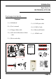
Introduction Section 1 INTRODUCTION Package Contents Contents Optional Item A. (1) Mainboard F. (1) COM2 port cable B. (1) Users manual G. (1) USB2.0 Cable C. (1) Floppy ribbon cable H. (1) Bluetooth Module D. (1) ATA-66/100 Hard drive ribbon I. (1) SPD650 card cable E.
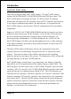
Introduction System Overview This board is designed with Intel® 845PE chipset. The Intel® 845PE chipset includes MCH(FW82845PE), ICH4(FW82801DB) and FWH three chips. The Intel® 845PE chipset is designed for Intels FC-PGA2 socket 478 package architecture and support the 4X capability of the AGP 2.0 Interface Specification. A new chipset component interconnect, the hub interface, is designed into the Intel® 845PE chipset to provide more efficient communication between chipset components.
Introduction Chipset Components The Intel® 845PE chipset consists of the Memory Controller Hub (MCH), the I/O Controller Hub (ICH4) and the Firmware Hub (FWH). ! Memory Controller Hub (MCH) The MCH provides the interconnect between the DDR SDRAM and the system logic. It integrates: - Support for single processor with a data transfer rate of 400/533MHz. - 200/266/333MHz DDR SDRAM interface supporting 2GB of DDR SDRAM. - 4X 1.5V AGP interface (Only support 1.5V on AGP interface).
Introduction Intel Pentium 4 processors Formally known as the Willamette, the PentiumTM 4 is the next PEneration IA-32 processor from Intel. This next generation design is based upon a new microarchitecture that brings higher clock speeds and performance than previous processors could deliver. Among other advanced features the Pentium 4 offers Streaming SIMD extensions 2, Advanced Dynamic Execution, Hyper Pipelined Technology, and a data transfer rate of 400/533MHz system bus.
Introduction Hyper Pipelined Technology & 400/533MHz System Bus Hyper Pipelined Technology doubles the pipeline depth the Pentium 4 delivers to 20 stages. This significantly increases the performance and frequency capabilities. Pentium 4 also introduces a 400/533MHz system bus as opposed to the 100 and 133MHz bus seen in previous Pentium III processors. This allows 3.2Gbytes per second of throughput while the Pentium III had a limited 1.06Gbyte/s throughput.
Introduction Accelerated Graphics Port (AGP or A.G.P.) Typically, 3D graphics rendering requires a tremendous amount of memory, and demands ever increasing throughput speed as well. As 3D products for the personal computer become more and more popular, these demands will only increase. This will cause a rise in costs for both end users and manufacturers. Lowering these costs as well as improving performance is the primary motivation behind AGP.
Introduction Bandwidth Overview Table 1 provides a summary of the bandwidth requirements for the Intel® 845PE chipset. Interface Clock Speed (MHz) Samples Per Clock (Mega-samples/s) Data Rate Data Width (Bytes) Bandwidth (MB/s) CPU Bus 100/133 4 400/533 8 3200/4264 DDR SDRAM 100/133/166 2 200/266/333 8 1600/2128/2664 AGP 2.0 66.6 4 266 4 1066 Hub Link 66.6 4 266 1 266 PCI 2.2 33.3 1 33.
Introduction Mainboard Form-Factor The board is designed with ATX form factor - the latest industry standard of chassis. The ATX form factor is essentially a Baby-AT baseboard rotated 90 degrees within the chassis enclosure and a new mounting configuration for the power supply. With these changes the processor is relocated away from the expansion slots, allowing them all to hold full length add-in cards.
Introduction I/O Shield Connector The board is equipped with an I/O back panel. Please use the appropriate I/O shield (figure 3). RJ-45 LAN (Optional) Joystick/Midi Port Parallel Port PS/2 Mouse PS/2 Keyboard USB2.0 ports COM1 Line-out Line-in Mic-in Figure 3: I/O back panel layout Power-On/Off (Remote) The board has a single 20-pin and 4-pin connector for ATX or ATX12V power supplies (Figure 4).
Introduction System Block Diagram Pentium 4 Processor 478 pin Package 100/133MHz 4X (1.
.A=JKHAI Section 2 FEATURES Mainboard Features: ! PROCESSOR ® - Intel Pentium 4 Processor with FC-PGA2 socket 478 package: Operating at 1.4 ~ 2.8GHz - Supports Hyper-Threading Technology Enabling the functionality of Hyper-Threading Technology for your computer system requires ALL of the following platform Components: " CPU: ® ® An Intel Pentium 4 Processor with HT Technology. ® " Chipset: An Intel Chipset that supports HT Technology.
.A=JKHAI ! ONBOARD I/O - Winbond 83627HF-AW LPC I/O integrated with K/B , Mouse, FDD, Parallel and Serial, Fast IR and Power-ON controllers ! ONBOARD PCI / IDE Intel 82801DB/ICH4 Controller - PCI Rev. 2.
.A=JKHAI ! EXTENDED FUNCTION - Supports Hardware Monitoring Function by W83627HF-AW - Supports exclusive KBPO (Keyboard Power ON) Function - Supports STR (Suspend To RAM) power saving Function - Supports Wake-On-LAN Function - Supports CPU Clock and Ratio Settings via BIOS - Supports CPU Vcore, AGP and memory Voltage Settings via BIOS - Supports Magic Health and Easy Boot Function - Supports Asynchronous Transfer Mode between PCI & FSB - Supports Programmable AGP/PCI clock output frequency with 1MHz i
.A=JKHAI Page Left Blank Page 2-4
Installation Section 3 INSTALLATION Page 3-1
Installation Mainboard Layout Page 3-2
Installation Easy Installation Procedure The following must be completed before powering on your new system: 3-1. 3-2. CPU Installation Jumper Settings 3-3. 3-4. 3-5. System Memory Configuration Device Connectors External Modem Ring-in Power ON and Keyboard Power ON Functions (KBPO) STR Function 845PE Platform AGP Card 4X/1.5V Protection 3-6. 3-7. Section 3-1 CPU Installation Figure 2 Figure 1 Pin 1 Step 1 Step 2 Open the socket by raising the actuation lever.
Installation Figure 3 Figure 4 Step 3 Step 4 Close the socket by lowering and locking the actuation lever. Apply thermal compound to the top of the CPU and install the heatsink as shown. Figure 5 Step 5 Figure 6 Step 6 Install the cooling fan assembly. Press Plug the CPU fan into the CPU fan conthe two clips in the direction of the nector (FAN1). arrows shown in Figure 5 to secure the The installation is complete. assembly to the CPU socket.
Installation Section 3-2 Jumper Settings JBAT1 CMOS Clear 1-2: Normal (Default) 2-3: Clear CMOS Page 3-5
Installation Section 3-3 System Memory Configuration Memory Layout The mainboard accommodates two PC1600/PC2100/2700 184-pin DIMMs (Dual In-line Memory Modules): Supports up to 2.0GB of 200/266/333MHz DDR SDRAM. Supports up to 2 DDR DIMMs (refer to Table 1). Supports DDR 200/266/333 unregistered 184-pin non-ECC DDR SDRAM DIMMs. Supports configurations defined in the JEDEC DDR DIMM specification NOTE:The mainboard does not support double-sided x 16 DDR DIMMs.
Installation DIMM Module Installation Figure 8 displays the notch on the DDR DIMM memory module. DIMMs have 184 pins and one notch that matches with the DDR DIMM socket. DIMM modules are installed by placing the chip firmly into the socket and pressing straight down as shown in figure 9 until the white clips close and the module fits tightly into the DIMM socket (figure 10). CENTER KEY ZONE (2.
Installation Section 3-4 Device Connectors RJ-45 LAN (Optional) Joystick/Midi Port Parallel Port PS/2 Mouse PS/2 Keyboard USB2.0 ports COM1 Line-out Line-in Mic-in Figure 11 - I/O Ports FAN1 / FAN2 / FAN3: CPU/Power/Chassis Fan Power Connectors FAN1 FAN2: Power Fan GND +12V NC GND +12V Rotation FAN1: CPU Fan FAN3: Chassis Fan GND +12V Rotation FAN2 FAN3 WOL1:WOL (Wake On LAN) Connector Reserved for an NIC (Network Interface Card) to wake the system from power saving mode.
Installation IDE1: Ultra DMA-66/100 Primary IDE Connector (Blue) IDE2: Ultra DMA-66/100 Secondary IDE Connector (Blue) FLOPPY1: Floppy Controller Connector (Black) ATX1: ATX Power Connector (20-pin power connector) ATX2 COM2 ATX1 ATX2: ATX12V Power Connector (12V 4-pin power connector) Note: The board requires a minimum of 250 Watt ATX or ATX 12V power supply to operate. Your system configuration (amount of memory, add-in cards, peripherals, etc.
Installation FPCN1: Front Panel Audio Connector When headphones are plugged into the front panel headphone jack, the rear panel audio output connectors are disabled. If the front panel interface board is not connected to the front panel audio header, short pins 5 - 6 and 9 -10 on the front panel audio header. If these pins are not shorted, the rear panel audio connectors are inoperative. Settings Pins (5-6) & (9-10) Short (default): Only the Onboard Rear Audio Speaker can be used.
Installation USB2/3: USB port header for four USB2.0 ports. The USB3 is used to connect bluetooth module for wireless connection.
Installation ! Power On/Off This is connected to the power button on the case. Using the Soft-Off by Pwr-BTTN feature, you can choose either Instant Off (turns system off immediately), or 4 sec delay (push the button for 4 seconds before the system turns off). When the system is in 4 sec delay mode, suspend mode is enabled by pushing the button momentarily. ! Turbo LED indicator J3 ! IDE LED indicator LED on when onboard PCI IDE Hard disks are being accessed. ! IR Connector 1. VCC 2. CIRRX 3. IRRX J2 4.
Installation Section 3-5 External Modem Ring Power ON and Keyboard Power ON Functions (KBPO) Modem Ring Power ON Function The I/O chipset provides the two serial ports with the External Modem Ring-in Power ON function. Once you connect an external modem to COM1 or COM2, the mainboard enables you to turn on the system through remote and host dial-up control. Keyboard Power ON Function The mainboard features a keyboard power on function that enables you to turn on the power supply using a keypress.
Installation 3-6 STR (Suspend To RAM) Function This mainboard supports the STR (Suspend To RAM) power management scheme by maintaining the appropriate power states in the DDR SDRAM interface signals. The power source to the DDR SDRAM must be kept active during STR (ACPI S3). Advanced Configuration Power Interface (ACPI) provides many Energy Saving Features for operating systems that support Instant ON and QuickStartTM function. 1.
Installation 3-7 845PE Platform AGP Card 3.3V Protection The Intel® 845PE chipset supports 1.5 volt AGP graphics cards only. Using a 3.3 volt AGP card in an Intel® 845PE chipset-based board might damage the chipset on an 845PE-equipped mainboard. However, this mainboard features a protection function that prevents the system from powering on when a 3.3V AGP card is inadvertently inserted into the AGP slot. If this happens, we recommend you to follow these steps: Step 1: Remove the 3.
Installation Page Left Blank Page 3-16
BIOS Section 4 AWARD BIOS SETUP Main Menu Awards ROM BIOS provides a built-in Setup program which allows user to modify the basic system configuration and hardware parameters. The modified data is stored in a battery-backed CMOS, so that data will be retained even when the power is turned off. In general, the information saved in the CMOS RAM will stay unchanged unless there is a configuration change in the system, such as hard drive replacement or a device is added.
BIOS The main menu displays all the major selection items. Select the item you need to reconfigure. The selection is made by moving the cursor (press any direction (arrow key ) to the item and pressing the Enter key. An on-line help message is displayed at the bottom of the screen as the cursor is moved to various items which provides a better understanding of each function. When a selection is made, the menu of the selected item will appear so that the user can modify associated configuration parameters.
BIOS Notes: _ If the hard disk Primary Master/Slave and Secondary Master/Slave are set to Auto, then the hard disk size and model will be auto-detected. _ The Halt On: field is used to determine when to halt the system by the BIOS if an error occurs. _ Floppy 3 Mode support is a mode used to support a special 3.5-inch drive used in Japan. This is a 3.5-inch disk that stores 1.2 MB. The default setting for this is disabled.
BIOS Virus Warning During and after system boot up, any attempt to write to the boot sector or partition table of the hard disk drive halts the system and an error message appears. You should then run an anti-virus program to locate the virus. Keep in mind that this feature protects only the boot sector, not the entire hard drive. The default is Disabled. Enabled: Activates automatically when the system boots up causing a warning message to appear when anything attempts to access the boot sector.
BIOS MPS Version Control For OS Specifies the Multiprocessor Specification (MPS). Version 1.4 supports multiple PCI bus configurations by incorporating extended bus definitions. Enable this for Windows NT or Linux. For older operating systems, select Version 1.1. The default is 1.4. Options: 1.1, 1.4. HDD S.M.A.R.T. Capability The S.M.A.R.T. (Self-Monitoring, Analysis, and Reporting Technology) system is a diagnostics technology that monitors and predicts device performance. S.M.A.R.T.
BIOS Typematic Rate (Chars/Sec) This is the number of characters that will be repeated by a keyboard press. The default is 6. Options: 6 ~ 30 characters per second. Typematic Delay (msec) This setting controls the time between the first and the second character displayed by typematic auto-repeat. The default is 250. Options: 250/500/750/1000 msec. Security Option This category allows you to limit access to the System and Setup, or just to Setup. The default is Setup.
BIOS First /Second/Third/Other Boot Device The BIOS attempts to load the operating system from the devices in the sequence selected in these items. Options: Floppy, LS120, HDD-0, SCSI, CDROM, HDD-1, HDD-2, HDD-3, ZIP100, USB-FDD, USB-ZIP, USB-CDROM, USB-HDD, LAN, Disabled. Boot Other Device When enabled, the system searches all other possible locations for an operating system if it fails to find one in the devices specified under the first, second, and third boot devices. The default is Enabled.
BIOS 4-3 Advanced Chipset Features Choose the ADVANCED CHIPSET FEATURES option in the CMOS SETUP UTILITY menu to display following menu. Figure 4: Chipset Features Setup DRAM Timing Selectable For setting DRAM Timing, By SPD is follow Intel PC DDR SDRAM Serial Presence Detect Specification. Options: Manual, By SPD. CAS Latency Time Enables you to select the CAS latency time. The value is set at the factory depending on the DRAM installed.
BIOS Active to Precharge Delay This item specifies the number of clock cycles needed after a bank active command before a precharge can occur (sets the minimum RAS pulse width.). The default is by DRAM SPD. Options: 5, 6, 7. DRAM RAS# to CAS# Delay This item sets the timing parameters for the system memory such as the CAS (Column Address Strobe) and RAS (Row Address Strobe). The default is by DRAM SPD. Options: 2, 3.
BIOS Fast CS# When set to Enabled and when SDRAM interface is idle, CS# is asserted in the same time the SDRAM tracking transitions to active state. The fast CS# timing is also applicable for pipelined assertion that follows page hit cycle. Auto: This selection will Auto detect.
BIOS 4-4 Integrated Peripherals Figure 5: Integrated Peripherals Notes: If you do not use the Onboard IDE connector, then you will need to set Onboard Primary PCI IDE: Disabled and Onboard Secondary PCI IDE: Disabled The Onboard PCI IDE cable should be equal to or less than 18 inches (45 cm.). Init Display First If two video cards are used (1 AGP and 1 PCI) this specifies which one will be the primary display adapter. The default is PCI Slot. Options: PCI Slot, AGP.
BIOS Onboard IDE Device Setup Scroll to Onboard IDE Device Setup and press . The following screen appears: On-Chip Primary PCI IDE The integrated peripheral controller contains an IDE interface with support for two IDE channels. Select Enabled (default) to activate each channel separately. Options: Enabled, Disabled.
BIOS IDE HDD Block Mode IDE Block Mode allows the controller to access blocks of sectors rather than a single sector at a time. The default is Enabled. Enabled: Enable IDE HDD Block Mode. Provides higher HDD transfer rates. Disabled: Disable IDE HDD Block Mode. Onboard PCI Device Setup Scroll to Onboard PCI Device Setup and press . The following screen appears: USB Controller Enables the all USB controller. Options: Disabled, Enabled. USB 2.0 Controller Enables the EHCI (USB2.0) controller.
BIOS AC97 Audio This item allows you to decide to auto or disable the chipset family to support AC97 Audio. The function setting AC97 Audio Codec states. The system default is Auto. Options: Auto, Disabled. Onboard PCI LAN (Optional) Enables the onboard LAN feature. Options: Enabled, Disabled. Game Port Address Select an address for the Game port. Options: 201 (default), 209, Disabled. Midi Port Address Select an address for the Midi port. Options: 290, 300, 330, Disabled (default).
BIOS Onboard I/O Chip Setup Scroll to Onboard I/O Chip Setup and press . The following screen appears: Onboard FDC Controller Select Enabled if your system has a floppy disk controller (FDC) installed on the system board and you wish to use it. If you install and-in FDC or the system has no floppy drive, select Disabled in this field. Options: Enabled, Disabled. Onboard Serial Port 1/2 Select an address and corresponding interrupt for the first and second serial ports.
BIOS UR2 Duplex Mode This item allows you to select IR half/full duplex function. Options: Half, Full. Use IR Pins This item allows you to select IR transmission routes, one is RxD2, TxD2 (COM Port) and the other is IR-Rx2Tx2. Options: IR-Rx2Tx2, RxD2, TxD2. Onboard Parallel Port This field allows the user to configure the LPT port. Options: 378/IRQ7, 278/IRQ5, 3BC/IRQ7, Disabled. Parallel Port Mode This field allows the user to select the parallel port mode. Options: SPP, EPP, ECP, ECP+EPP.
BIOS 4-5 Power Management Setup Choose the POWER MANAGEMENT SETUP in the CMOS SETUP UTILITY to display the following screen. This menu allows the user to modify the power management parameters and IRQ signals. In general, these parameters should not be changed unless its absolutely necessary. Figure 6: Power Management ACPI Suspend Type This item allows you to select S1(POS) or S3(STR) function. When set to S3 (STR) or S1&S3 the following two fields become available.
BIOS Run VGABIOS if S3 Resume This determines whether or not to enable the system to run the VGA BIOS when resuming from S3(STR) or S1&S3. Options: Auto, Yes, No. S3 KB Wake-up Function This determines whether or not to enable keyboard/mouse activity to awaken the system from S3(STR) or S1&S3. Options: AnyKey or Mouse, By PowerOn Func., AnyKey, Mouse. POWER ON Function Enables computer power on by keyboard, mouse, or hotkey activity. The default is Hot KEY.
BIOS PWRON After PWR-Fail This item enables your computer to automatically restart or return to its last operating status after power returns from a power failure. Off: The system stays off after a power failure. Former-Sts: The system returns to the state it was in just prior to the power failure. Power Management Use this to select your Power Management selection. The default is User define. Max. saving: Maximum power savings. Inactivity period is 1 minute in each mode. Min. saving: Minimum power savings.
BIOS MODEM Use IRQ Name the interrupt request (IRQ) line assigned to the modem (if any) on your system. Activity of the selected IRQ always awakens the system. Default is IRQ 3. Options: N/A, 3, 4, 5, 7, 9, 10, 11 Suspend Mode enabled and after the set time of system inactivity, all devices except the CPU will be shut off. Options: Disabled, 1, 2, 4, 8, 12, 20, 30, 40 Min and 1 Hour.
BIOS RTC Alarm Resume When enabled, you can set the date and time in the following two fields. Any event occurring at the specified date or time awakens the system from power savings mode. ** Reload Global Timer Events ** Primary/Secondary IDE 0/1 Any activity occuring on these channels awakens the system from power savings mode. FDD, COM, LPT Port When enabled, any event occurring on these ports awakens the system from power savings mode.
BIOS 4-6 PNP/PCI Configuration The PNP/PCI configuration program is for the user to modify the PCI/ISA IRQ signals when various PCI/ISA cards are inserted in the PCI or ISA slots. WARNING: Conflicting IRQs may cause the system to not find certain devices. Figure 7: PNP/PCI Configuration Setup Reset Configuration Data This setting allows you to clear ESCD data. The default is Disabled Disabled:Normal Setting.
BIOS PCI/VGA Palette Snoop This item is designed to overcome problems that can be caused by some nonstandard VGA cards. This board includes a built-in VGA system that does not require palette snooping so you must leave this item disabled. Options: Enabled, Disabled. PCI Latency Timer (CLK) The latency timer defines the minimum amount of time, in PCI clock cycles, that the bus master can retain the ownership of the bus. Options: 0-255.
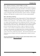
BIOS Interrupt requests are shared as shown below: INT A AGP Slot INT B INT C INT D AC97/MC97 V Slot 1 V Slot 2 V Slot 5 V Onboard LAN (Optional) V V V Onboard USB3 V USB 2.0 SM BUS INT G V Slot 4 Onboard USB2 INT F V Slot 3 Onboard USB1 INT E V V V IMPORTANT! If using PCI cards on shared slots, make sure that the drivers support Shared IRQ or that the cards dont need IRQ assignments.
BIOS 4-7 PC Health Status 33oC/91oF 59oC/138oF 0 RPM 0 RPM 0 RPM 1.50V 1.75V 2.50V 4.97V 12.12V -12.28V -5.09V 3.48V 4.89V Figure 8: PC Health Status CPU Warning Temperature Sets the temperature at which the computer will respond to an overheating CPU. The default is Disabled. Options: Disabled, 50OC/122OF ~ 70OC/158OF. Current CPU Temperature Displays the current CPU temperature. Current System Temperature Displays the current system temperature.
BIOS Vdimm(V) The voltage level of the DRAM. ± 5V, ± 12V, VBAT(V), 5VSB(V) The voltage level of the switching power supply. ACPI Shutdown Temperature This is the temperature that the computer will turn off the power to combat the effects of an overheating system. (requires ACPI to be enabled in Power Management BIOS and ACPI compliant operating system.) The default is Disabled. Options available are 60oC/140oF to 95oC/203oF in increments of 5oC.
BIOS 4-8 Frequency/Voltage Control [8X] 66 33 1.75V 1.75V 1.50V 1.50V 2 . 5 0V 2 . 5 0V Figure 9: Frequency/Voltage Control CPU Clock Ratio Use this item to select a multiplier for the system frontside bus (FSB) frequency. The value of the multiplier must be set so that: Multiplier x Frontside Bus Frequency = CPU Clock Speed For example, if you have a processor that is rated to run at 450 MHz and the system is running a frontside bus frequency of 100 MHz, you should select a multiplier of 4.
BIOS CPU FSB/SPEED Enables you to set the CPU frontside bus speed. The default is 100 MHz. Enables you to adjust CPU clock 1MHz by step. Pressing Enter displays the following screen: Key in the DEC (decimalism) number for the CPU FSB/SPEED. Memory Frequency Enables you to select a ratio of the Double Data Rate Synchronous DRAM to match the installed DRAM frequency 200 or 266 MHz. We recommend that you leave this item at the default value.
BIOS AGP/PCI subtle tuning Enables you to set the AGP/PCI frequency, enables you to subtle tuning AGP clock 1MHz by step. The default is 66 MHz. Pressing Enter displays the following screen: Key in the DEC (decimalism) number for the AGP/PCI subtle tuning. In the following items, Default Voltage indicates the original factory value, and New Voltage indicates the value that you assign. CPU Vcore Voltage This item allows you to set the CPU Vcore voltage. The default is -0.075V. Options: -0.100V to +0.
BIOS Clock Generation for EMI Scroll to Clock Generation for EMI and press . The following screen appears: Auto Detect PCI Clk When enabled the mainboard automatically disables the clock source for a PCI slot which does not have a module in it, reducing EMI (ElectroMagnetic Interference). The default is Enabled. Spread Spectrum Modulated If you enable spread spectrum, it can significantly reduce the EMI (ElectroMagnetic Interference) generated by the system.
BIOS 4-10 Supervisor/User Password Setting These items are used to install a password. A Supervisor password takes precedence over a User password, and the Supervisor limits the activities of a User. You can set either a supervisor or user password, or both of them: Supervisor password: authorized to enter and change the options of the setup menus. User password: authorized to enter, but not authorized to change the options of the setup menus.
BIOS 4-11 Exiting BIOS Save & Exit Setup Pressing on this item asks for confirmation: Save to CMOS and EXIT (Y/N)? Y Pressing Y stores the selections made in the menus in CMOS a special section of memory that stays on after you turn your system off. The next time you boot your computer, the BIOS configures your system according to the Setup selections stored in CMOS. After saving the values the system is restarted again.
Drivers Installation Section 5 Driver Installation Easy Driver Installation INTEL 845G/845GL/845GE/845PE CHIPSET DRIVER INTEL CHIPSET INF FILES INTEL APPLICATION ACCELERATOR ALC 201A/650 AC97 AUDIO DRIVER (Optional) VIA 6105 LAN DRIVER ACROBAT READER CD EXPLORER EXIT Insert the bundled CD-disk. Step 1 : Click INTEL CHIPSET INF FILES. Install all components recommended. Step 2 : Click INTEL APPLICATION ACCELERATOR. to install ultra storage driver.
Drivers Installation ALC650 Configuration Setup (6 Channel) ! To enable ALC650 Function 1. Right-click Sound Effect button in the tool bar display currently selected Titles. Select Sound Manager. Sound Effect: 2. Click Sound Effect button and select Environment from the drop-down menu.
Drivers Installation Equalizer: 3. Click Equalizer and setup the value of dB. Speak Configutation: 4. Click Line in and Mic in buttons to enable 6 channel function as this is required for the ALC650.
Drivers Installation Speak Configutation: 5. The selected screen appears. Speaker Test: 6. Click Speaker Test button and click on the speakers directly which show on the screen to test it.
Drivers Installation General: 7. General Information for user reference.
Drivers Installation Page Left Blank Page 5-6
Appendix Appendix A A-1 Avance® Media Player User’s Guide Avance® Media Player Platform J B 3 1 4 A 7 8 5 2 C 6 D I E F G H Functional Descriptions A. Playback Windows Display Playback windows displays the following mode information: 1. Playback Time Display 2. Voice Cancellation Mode Display 3. Pitch Mode Display 4. Surround Sound Mode Display B. Playback Function Controls There are 8 selectable functions for the playback: 1. Volume control High/Low Adjustment Bar. 2.
Appendix 3. Repeat mode Choice of Repeat, All Repeat, Random or No Repeat Mode. 4. Mute Mute On/Off Mode select. 5. Voice cancellation Voice Cancellation On/Off Mode select for Karaoke. 6. Surround mode A total of 26 Surround Sound mode select as shown in the table below.
Appendix F. Title/Play List Edit Controls There title/play list controls include “Add”, “Del”, “Clear”, “Load”, & “Store”. 1. Add Add to the Title/Play List. 2. Del Remove form the Title/Play List. 3. Clear Clear the Title/Play Lost. 4. Load Load Title/Play List. 5. Store Save Title/Play List. G. Title/Play List Scroll bar Scroll Up/Down the Title/Play List. H. Recording Function Controls The recording function controls include “Input”, “Save:, “New”, “Rec”, “Stop”, & “Play”. 1.
Appendix Page Left Blank A-4
Appendix Appendix B B-1 Update Your System BIOS Download the xxxxx.EXE file corresponding to your model form the our website to an empty directory on your hard disk or floppy. Run the downloaded xxxxx.EXE file and it will self extract. Copy these extracted files to a bootable DOS floppy disk. Note: The DOS floppy disk should contain NO device drivers or other programs. 1. Type “A:\AWDFLASH and press Key. 2. You will see the following setup on screen. 3. Please key in the xxxxx.bin BIOS file name.
Appendix 5. Key in File Name to save previous BIOS to file. XXXX XXXXX xxxxx.bin xxxxx.bin 6. Are you sure to program (y/n), please key in [Y] to start the programming. XXXX XXXXX xxxxx.bin xxxxx.bin 7. The programming is finished. XXXX XXXXX xxxxx.
Appendix Appendix C C-1 EEPROM BIOS Remover Do not remove the BIOS chip, unless instructed by a technician and only with a PLCC IC extractor tool. The BIOS socket may be damaged if using an improper method to replace the BIOS chip.
Appendix Page Left Blank C-2
Appendix Appendix D D-1 GHOST 7 Quick User’s Guide (Optional) Installation is very easy. You only need to copy the Ghost7 folder or Ghost.exe to your hard disk. Main Menu Description of Menu Ghost clones and backs up Disk and Partition.
Appendix Disk There are 3 hard disk functions: 1. Disk To Disk (disk cloning) 2. Disk To Image (disk backup) 3. Disk From Image (restore backup) Important! 1. To use this function, the system must have at least 2 disks. Press the Tab key to move the cursor. 2. When restoring to a destination disk, all data in that disk will be completely destroyed. Disk To Disk (Disk Cloning) 1. Select the location of the Source drive. 2. Select the location of the Destination drive.
Appendix 3. When cloning a disk or restoring the backup, set the required partition size as shown in the following figure. 4. Click OK to display the following confirmation screen. Select Yes to start. Disk To Image (Disk Backup) 1. Select the location of the Source drive.
Appendix 2. Select the location for storing the backup file. 3. Click OK to display the following confirmation screen. Select Yes to start. Disk From Image (Restore Backup) 1. Select the Restoring file.
Appendix 2. Select the Destination drive of the disk to be restored. 3. When restoring disk backup, set the required partition size as shown in the following figure. 4. Click OK to display the following confirmation screen. Select Yes to start.
Appendix Partition There are 3 partition functions: 1. Partition To Partition (partition cloning) 2. Partition To Image (partition backup) 3. Partition From Image (restore partition) Partition To Partition (Partition Cloning) The basic unit for partition cloning is a partition. Refer to disk cloning for the operating method. Partition To Image (Partition Backup) 1. Select the disk to be backed up.
Appendix 2. Select the first partition to be backed up. This is usually where the operating system and programs are stored. 3. Select the path and file name to store the backup file. 4. Is the file compressed? There are 3 options: (1) No: do not compress data during backup (2) Fast: Small volume compression (3) High: high ratio compression. File can be compressed to its minimum, but requiring longer execution time.
Appendix 5. Select Yes to start performing backup. Partition From Image (Restore Partition) 1. Select the backup file to be restored. 2. Select the source partition.
Appendix 3. Select the disk to be restored. 4. Select the partition to be restored. 5. Select Yes to start restoring. Check This function is to check possible error caused by defective FAT or track during backup or restoring.
Appendix How to Reinstall Windows in 2 Minutes This chapter guides you how to setup your computer properly and, if necessary, reinstall Windows in 2 minutes. Ghost provides different methods to complete this task. The following two sections explain how to create an emergency Recover Floppy and Recover CD: Emergency Recover Floppy Divide a hard disk into two partitions. The first partition is to store the operating system and application programs.
Appendix (2) After booting, the screen displays the Menu. Select Backup or Restore: Since the user may install other applications in the future, he/she may alter Autoexec.bat file to back up or restore the user-defined Image file as follows: # Backup Back up Windows and application programs as a file (Recent. gho). Command is: Ghost clone,mode=pdump,src=1:1,dst=d:\Recent.gho -fx sure -rb # Restore Restore types include [General Windows] and [Windows and Application Programs].
Appendix Recover CD The following is a simple guide to create a recover CD: 1. First, create a recover floppy disk contains the following with any copy program such as Easy CD Create (Note 2) : Bootable files (Command.com and Io.sys and MSDOS.SYS) Config.sys (Configuration setup file) Autoexec.bat (Auto-execution batch file) Mscdex.exe (CD-Rom execution file) Ghost.exe (Ghost execution file) Oakcdrom.sys (ATAPI CD-ROM compatible driver) The content of Config.sys is: DEVICE=Oakcdrom.