EP-3VWM A Soc ket 370 Pr ocessor based Sock Processor mainboard (133/100/66MHz) Supports Suppor ts PC100 SDRAM Module TRADEMARK All products and company names are trademarks or registered trademarks of their respective holders. These specifications are subject to change without notice. Manual Revision 1.
EP-3VWM User Notice No part of this product, including the product and software may be reproduced, transmitted, transcribed, stored in a retrieval system, or translated into any language in any form without the express written permission of EPoX Computer Company (hereinafter referred to as EPoX) except for documentation kept by the purchaser for backup purposes.
EP-3VWM Technical Support Services If you need additional information, help during installation or normal use of this product, please contact your retailer. Your retailer will have the most current information about your configuration. If your retailer cannot help, you may visit our online technical support website and/or contact our support technicians at the locations listed below. Record your serial number before installing your EP-3VWM mainboard.
EP-3VWM Table of Contents Section 1 Introduction Page Components Checklist ........................................ 1-1 Overview EP-3VWM Form-Factor ..................................... 1-2 I/O Shield Connector .......................................... 1-3 Power-On/Off (Remote) ..................................... 1-3 System Block Diagram ........................................ 1-4 Section 2 Features EP-3VWM Features ............................................
EP-3VWM Appendix Appendix A Memory Map ....................................................... A-1 I/O Map ................................................................ A-1 Timer & DMA Channels Map ............................. A-2 Interrupt Map ....................................................... A-2 RTC & CMOS RAM Map .................................... A-3 Appendix B POST Codes ......................................................... B-1 Appendix C Load Setup Defaults .........................
EP-3VWM Page Left Blank
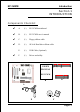
EP-3VWM Introduction Section 1 INTRODUCTION Components Checklist ü A. (1) EP-3VWM mainboard ü B. (1) EP-3VWM users manual ü C. (1) Floppy ribbon cable ü D. (1) ATA-66 Hard drive ribbon cable E. (1) USB Cable (Optional) F.
Introduction EP-3VWM EP-3VWM Form-Factor The EP-3VWM is designed with MicroATX form factor - the new industry standard of chassis. MicroATX form factor is essentially a Baby-AT baseboard rotated 90 degrees within the chassis enclosure and a new mounting configuration for the power supply. With these changes the processor is relocated away from the expansion slots, allowing them all to hold full length add-in cards.
EP-3VWM Introduction I/O Shield Connector The EP-3VWM is equipped with an I/O back panel. Please use the appropriate I/O shield (figure 3). parallel port Joystick/Midi port PS/2 Mouse PS/2 KEYBOARD USB port COM1 VGA1 Figure 3: I/O back panel layout Speaker Line_in MIC Power-On/Off (Remote) The EP-3VWM has a single 20-pin connector for ATX power supplies. For ATX power supplies that support the Remote On/Off feature, this should be connected to the systems front panel for system Power On/Off button.
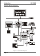
Introduction EP-3VWM System Block Diagram Figure 5: System Block Diagram Page 1-4
EP-3VWM Features Section 2 FEATURES EP-3VWM Features: EP-3VWM is based on the Socket 370 Processors including PPGA & FCPGA operating at 300 ~ 800MHz. Designed with VIA VT8601 AGPset. Supports up to 512MB of DRAM (minimum of 32 MB) on board (please see Section 3-2). Supports (3) 32 bit PCI slots, (1) 16 bit ISA slot, (1) AMR slot and provides (2) independent high performance PCI IDE interfaces capable of supporting PIO Mode 3/4 and Ultra DMA 33/66 devices.
Features EP-3VWM Built-in ATX 20-pin power supply connector. Software power-down when using Windows® 95/98 or Windows®2000. Supports ring-in feature (remote power-on through external modem, allows system to be turned on remotely). Resume by Alarm - Allows your system to turn on at a preselected time. Power Loss Recovery - In the event of a power outtage your system will automatically turn itself back on without user intervention. Supports CPU Hardware sleep and SMM (System Management Mode).
EP-3VWM Installation Section 3 INSTALLATION Page 3-1
Installation EP-3VWM EP-3VWM Detailed Layout Figure 1 Page 3-2
EP-3VWM Installation Easy Installation Procedure The following must be completed before powering on your new system: 3-1. CPU Insertion 3-2. Jumper Settings 3-3. System memory Configuration 3-4. Device Connectors Section 3-1 CPU Insertion CPU Insertion Step 1 Open the socket by raising the actuation lever. Figure 2 Step 2 Insert the processor. Figure 3 Ensure proper pin 1 orientation by aligning the FC-PGA corner marking with the socket corner closest to the actuation arm tip.
Installation EP-3VWM Step 3 Close the socket by lowering and locking the actuation lever. Figure 4 Note: Intels reference design thermal solution is an active heatsink; an extruded aluminum heatsink based and a fan attached to the top on the fin array.
EP-3VWM Installation Section 3-2 Jumper Settings The EP-3VWM motherboard was designed with very few jumpers to make your installation faster and easier. JP1 CMOS Clear JP1 = 1-2 Normal (Default) = 2-3 Clear CMOS 1 JP3 1 JP20 JP18 JP19 JP21 JP23 JP24 CPU Frequency Ratio Select 1 1 1 1 JP22 1 1 1 Power Loss Recovery JP3 = 1-2 Disabled = 2-3 Enabled JP21 JP19 JP18 JP20 FREQ. RAT IO 1-2 1-2 2-3 1-2 1.5X 2-3 2-3 2-3 2-3 2X 2-3 1-2 2-3 2-3 2.
Installation EP-3VWM Section 3-3 System Memory Configuration Memory Layout The EP-3VWM supports (2) PC100 168-pin DIMMs (Dual In-line Memory Module). The DIMMs is for SDRAM (Synchronized DRAM) only. DIMM SDRAM may be 83MHz (12ns), 100MHz (10ns) or 125MHz (8ns) bus speed. If you use both 50ns and 60ns memory you must configure your BIOS to read 60ns. When using Synchronous DRAM we recommend using the 4 clock variety over the 2 clock.
EP-3VWM Installation DIMM Module Installation Figure 7 displays the notch marks and what they should look like on your DIMM memory module. DIMMs have 168-pins and two notches that will match with the onboard DIMM socket. DIMM modules are installed by placing the chip firmly into the socket at a 90 degree angle and pressing straight down (figure 8) until it fits tightly into the DIMM socket (figure 9). LEFT KEY ZONE (UNBUFFERED) CENTER KEY ZONE (3.
Installation EP-3VWM Section 3-4 Device Connectors parallel port PS/2 Mouse Joystick/Midi port USB port PS/2 KEYBOARD COM1 VGA1 Figure 10 Speaker Line_in MIC J2,J3: Chassis Panel Connector Power LED, Speaker, Reset, Turbo LED, HDD LED, IR Conn.
EP-3VWM Installation MODEM_IN: Telephony Connector Pin1(Audio_in), Pin2/Pin3(GND), Pin4(Mic-out to Modem) COM2: RS232 COM2 Connector USB2: USB port header pins for adding two additional USB ports. VCC 6 1 GND -Data +Data +Data -Data GND VCC 5 10 USB port header pin descriptions.
Installation EP-3VWM Device Connectors (continued) (This is connected to the power button on the case. Using the Soft-Off by Pwr-BTTN feature, you can choose either Instant Off (turns system off immediatly), or 4 sec delay (you need to hold the button down for 4 seconds before the system turns off). When the system is in 4 sec delay mode, there is a special feature to make the system to go into suspend mode when the button is pressed momentarily).
EP-3VWM BIOS Section 4 AWARD BIOS SETUP Main Menu Awards ROM BIOS provides a built-in Setup program which allows user to modify the basic system configuration and hardware parameters. The modified data will be stored in a battery-backed CMOS, so that data will be retained even when the power is turned off. In general, the information saved in the CMOS RAM will stay unchanged unless there is a configuration change in the system, such as hard drive replacement or a device is added.
BIOS EP-3VWM The menu displays all the major selection items. Select the item you need to reconfigure. The selection is made by moving the cursor (press any direction key ) to the item and pressing the Enter key. An on-line help message is displayed at the bottom of the screen as the cursor is moved to various items which provides a better understanding of each function. When a selection is made, the menu of the selected item will appear so that the user can modify associated configuration parameters.
EP-3VWM BIOS NOTE: If the hard disk Primary Master/Slave and Secondary Master/ Slave are set to Auto, then the hard disk size and model will be auto-detected. NOTE: The Halt On: field is used to determine when to halt the system by the BIOS if an error occurs. NOTE: Floppy 3 Mode support is a mode used to support a special 3.5 drive used in Japan. This is a 3.5 disk that stores only 1.2 MB, the default setting for this is disabled.
BIOS EP-3VWM Virus Warning: During and after the system boots up, any attempt to write to the boot sector or partition table of the hard disk drive will halt the system and an error message will appear. You should then run an anti-virus program to locate the virus. Keep in mind that this feature protects only the boot sector, not the entire hard drive. The default value is Disabled.
EP-3VWM BIOS Quick Power On Self Test: This category speeds up the Power On Self Test (POST). The default is Enabled. Enabled: This setting will shorten or skip of the items checked during POST. Disabled: Normal POST. First /Second/Third/Other Boot Device: The BIOS attempts to load the operating system from the devices in the sequence selected in these items. The choice: Floppy, LS/ZIP, HDD, SCSI, CDROM, Disabled.
BIOS EP-3VWM Typematic Rate Setting: This determines the keystrokes repeat rate. The default is Disabled. Enabled: Allows typematic rate and typematic delay programming. Disabled: The typematic rate and typematic delay will be controlled by the keyboard controller in your system. Typematic Rate (Chars/Sec): This is the number of characters that will be repeated by a keyboard press. The default is 6. 6: 6 characters per second. 8: 8 characters per second. 10: 10 characters per second.
EP-3VWM BIOS Enabled: Video shadow is enabled. Disabled: Video shadow is disabled. C8000 - CBFFF Shadow: CC000 - CFFFF Shadow: D0000 - D3FFF Shadow: D4000 - D7FFF Shadow: D8000 - DBFFF Shadow: DC000 - DFFFF Shadow: These categories determine whether ROMs from option cards will be copied into RAM. This will be in 16K byte or 32K byte units, and the size will depend on chipset of the option card. Enabled: Optional shadow is enabled. Disabled: Optional shadow is disabled.
BIOS EP-3VWM 4-3 Advanced Chipset Features Choose the CHIPSET FEATURES SETUP in the CMOS SETUP UTILITY menu to display following menu. Figure 4: Chipset Features Setup Bank 0/1, 2/3 DRAM Timing: This value in this field is set by the system board manufacturer. The default is SDRAM Fast. The Choice: SDRAM Fast, SDRAM Normal. SDRAM Cycle length: This setting defines the CAS timing parameter of the SDRAM in terms of clocks. The default is 3. 2: Provides faster memory performance.
EP-3VWM BIOS Enabled: This field enables the main memory (15~16MB) to remap to ISA BUS. Disabled: Normal Setting. Note: If this feature is enabled you will not be able to cache this memory segment. System BIOS Cacheable: This allows you to copy your BIOS code from slow ROM to fast RAM. The default is Disabled. Enabled: The option will improve system performance. However, if any program writes to this memory area, a system error may result. Disabled: System BIOS non-cacheable.
BIOS EP-3VWM USB Keyboard Support: This controls the activation status of an optional USB keyboard that may be attached. The default is disabled. Enabled: Enable USB keyboard support. Disabled: Disable USB keyboard support. OnChip Sound: Turn on/off onchip sound device. OnChip Modem: Turn on/off onchip software modem device. CPU to PCI Write Buffer: When enabled, up to four D words of data can be written to the PCI bus without interruting the CPU.
EP-3VWM BIOS 4-4 Integrated Peripherals Figure 5: Integrated Peripherals Note: If you do not use the Onboard IDE connector, then you will need to set Onboard Primary PCI IDE: Disabled and Onboard Secondary PCI IDE: Disabled Note: The Onboard PCI IDE cable should be equal to or less than 18 inches (45 cm.). OnChip IDE Channel0: The default value is Enabled. Enabled: Enables Onboard IDE primary port. Disabled: Disables Onboard IDE primary port. OnChip IDE Channel1: The default is Enabled.
BIOS EP-3VWM Primary Master PIO: The default is Auto. Auto: BIOS will automatically detect the Onboard Primary Master PCI IDE HDD Accessing mode. Mode 0~4: Manually set the IDE Programmed interrupt mode. Primary Slave PIO: The default is Auto. Auto: BIOS will automatically detect the Onboard Primary Slave PCI IDE HDD Accessing mode. Mode 0~4: Manually set the IDE Programmed interrupt mode. Secondary Master PIO: The default is Auto.
EP-3VWM BIOS Init Display First: If two video cards are used (1 AGP and 1 PCI) this specifies which one will be the primary display adapter. The default is PCI Slot. PCI Slots: PCI video card will be primary adapter. AGP: AGP video card will be primary adapter. IDE HDD Block Mode: IDE Block Mode allows the controller to access blocks of sectors rather than a single sector at a time. The default is Enabled. Enabled: Enabled IDE HDD Block Mode. Provides higher HDD transfer rates.
BIOS EP-3VWM Onboard Parallel port: This field allows the user to configure the LPT port. The default is 378H / IRQ7. 378H: Enable Onboard LPT port and address is 378H and IRQ7. 278H: Enable Onboard LPT port and address is 278H and IRQ5. 3BCH: Enable Onboard LPT port and address is 3BCH and IRQ7. Disabled: Disable Onboard Winbond Chips LPT port. Onboard Parallel Port Mode: This field allows the user to select the parallel port mode. The default is Normal. Normal: Standard mode.
EP-3VWM BIOS 4-5 Power Management Setup Choose the POWER MANAGEMENT SETUP in the CMOS SETUP UTILITY to display the following screen. This menu allows the user to modify the power management parameters and IRQ signals. In general, these parameters should not be changed unless its absolutely necessary. Figure 6: Power Management Setup ACPI Function: This option allows you to select ACPI Function. The default is Enabled. Enabled: Support ACPI function for new O.S Disabled: No Support ACPI function.
BIOS EP-3VWM User define: Allows user to define PM Timers parameters to control power saving mode. PM controlled APM: This option shows weather or not you want the Power Management to be controlled the Advanced Power Management (APM). The default is Yes. Yes: APM controls your PM No: APM does not control your PM Video Off Option: Tells you what time frame that the video will be disabled under current power management settings. The default is Standby.
EP-3VWM BIOS Delay 4 Second : Turns off the system after a 4 second delay. If momentary press of button, the system will go into Suspend Mode. Press the power botton again to take system out of Suspend Mode. VGA: When set to On (default), any event occurring at a VGA port will awaken a system which has been powered down. LPT & COM: When set to On (default), any event occurring at a COM(serial)/ LPT (printer) port will awaken a system which has been powered down.
BIOS EP-3VWM 4-6 PNP/PCI Configuration The PNP/PCI configuration program is for the user to modify the PCI/ISA IRQ signals when various PCI/ISA cards are inserted in the PCI or ISA slots. WARNING: Conflicting IRQs may cause the system to not find certain devices. Figure 7: PCI Configuration Setup PNP OS Installed: Do you have a PNP OS installed on your system. The default is No. Yes: Select if you are using a PNP OS. No: Select if your OS does not support PNP.
EP-3VWM BIOS Disabled: Normal Setting. Enabled: If you have plugged in some Legacy cards to the system and they were recorded into ESCD (Extended System Configuration Data), you can set this field to Enabled in order to clear ESCD. PCI/VGA Palette Snoop: Leave this field at Disabled. The choice: Enabled, Disabled. Assign IRQ For USB: This item allows BIOS to assign whether IRQ is with USB or not. If you have not connect the USB device. Can release the IRQ for other device. The default is Enabled.
BIOS EP-3VWM 4-7 PC Health Status 31oC/87oF 0oC/32oF 6135 RPM 0 RPM 1.62V 3.20V 3.22V 5.01V 12.12V Current CPU Temperature: This is the current temperature of the CPU. Current System Temperature: This is the Current temperature of the system. Current CPU FAN Speed: The current CPU fan speed in RPMs. Current Chassis FAN Speed: The current chassis fan speed in RPMs. CPU(V): The voltage level of the CPU(Vcore/Vtt). 3.3V, 5V, 12V: The voltage level of the switch power supply.
EP-3VWM BIOS 4-8 Frequency/Voltage Control Auto Detect DIMM/PCI Clk: When enabled the motherboard will automatically disable the clock source for a DIMM socket which does not have a module in it. Same applies for PCI slots. The default is Enabled. Enabled: Enables this option. Disabled: Disables this option. Spread Spectrum : The default is Enabled. Enabled: Enables this option. Disabled: Disables this option.
BIOS EP-3VWM 4-9 Defaults Menu Selecting Defaults from the main menu shows you two options which are described below Load Fail-Safe Defaults When you press on this item you get a confirmation dialog box with a message similar to: Load Fail-Safe Defaults (Y/N) ? N Pressing Y loads the BIOS default values for the most stable, minimal-performance system operations.
EP-3VWM BIOS 4-10 Supervisor/User Password Setting You can set either supervisor or user password, or both of then. The differences between are: supervisor password : can enter and change the options of the setup menus. user password : just can only enter but do not have the right to change the options of the setup menus. When you select this function, the following message will appear at the center of the screen to assist you in creating a password.
BIOS EP-3VWM 4-11 Exit Selecting Save & Exit Setup Pressing on this item asks for confirmation: Save to CMOS and EXIT (Y/N)? Y Pressing Y stores the selections made in the menus in CMOS a special section of memory that stays on after you turn your system off. The next time you boot your computer, the BIOS configures your system according to the Setup selections stored in CMOS. After saving the values the system is restarted again.
Appendix EP-3VWM Appendix A A-1 MEMORY MAP Address Range [00000-7FFFF] [80000-9FBFF] [9FC00-9FFFF] Size 512K 127K 1K [A0000-C7FFF] [C8000-DFFFF] 160K 96K [E0000-EEFFF] [EF000-EFFFF] 60K 4K [F0000-F7FFF] [F8000-FCFFF] [FD000-FDFFF] [FE000-FFFFF] 32K 20K 4K 8K Description Conventional memory Extended Conventional memory Extended BIOS data area if PS/2 mouse is installed Available for Hi DOS memory Available for Hi DOS memory and adapter ROMs Available for UMB Video service routine for Monochrome & C
Appendix [2F8-2FF] [360-36F] [378-37F] [3B0-3BF] [3C0-3CF] [3D0-3DF] [3F0-3F7] [3F8-3FF] EP-3VWM SERIAL port 2. NETWORK ports. PARALLEL port 1. MONOCHROME & PARALLEL port adapter. EGA adapter. CGA adapter. FLOPPY DISK controller. SERIAL port 1. A-3 TIMER & DMA CHANNELS MAP TIMER MAP: TIMER Channel 0 TIMER Channel 1 TIMER Channel 2 DMA CHANNELS: DMA Channel 0 DMA Channel 1 DMA Channel 2 DMA Channel 3 DMA Channel 4 DMA Channel 5 DMA Channel 6 DMA Channel 7 System timer interrupt. DRAM REFRESH request.
EP-3VWM 6 7 8 9 10 11 12 13 14 15 Appendix FLOPPY DISK (SMC CHIP). PARALLEL port 1. RTC clock. Available. Available. Available. PS/2 Mouse. MATH coprocessor. Onboard HARD DISK (IDE1) channel. Onboard HARD DISK (IDE1) channel. A-5 RTC & CMOS RAM MAP RTC & CMOS: 00 Seconds. 01 Second alarm. 02 Minutes. 03 Minutes alarm. 04 Hours. 05 Hours alarm. 06 Day of week. 07 Day of month. 08 Month. 09 Year. 0A Status register A. 0B Status register B. 0C Status register C. 0D Status register D.
Appendix 16 17 18 19-2d 2E-2F 30 31 32 33 34-3F 40-7F A-4 EP-3VWM Base memory high byte. Extension memory low byte. Extension memory high byte. Reserved for extension memory low byte. Reserved for extension memory high byte. DATE CENTURY byte. INFORMATION FLAG. Reserve. Reserved for CHIPSET SETTING DATA.
Appendix EP-3VWM Appendix B B-1 POST CODES For BIOS 6.0 Code POST (hex) CFh C0h C1h C3h C5h 0h1 02h 03h 04h 05h 06h 07h 08h 09h 0Ah DESCRIPTION Test CMOS R/W functionality. Early chipset initialization: - Disable shadow RAM - Disable L2 cache (socket 7 or below) - Program basic chipset registers Detect memory - Auto-detection of DRAM size, type and ECC. - Auto-detection of L2 cache (socket 7 or below) Expand compressed BIOS code to DRAM Call chipset hook to copy BIOS back to E000 & F000 shadow RAM.
Appendix 0Ch 0Dh 0Eh 0Fh 10h 11h 12h 13h 14h 15h 16h 17h 18h 19h 1Ah 1Bh 1Ch 1Dh 1Eh 1Fh 20h 21h 22h 23h B-2 EP-3VWM 3. Reset keyboard for Winbond 977 series Super I/O chips. Reserved Reserved Test F000h segment shadow to see whether it is R/Wable or not. If test fails, keep beeping the speaker. Reserved Auto detect flash type to load appropriate flash R/W codes into the run time area in F000 for ESCD & DMI support. Reserved Use walking 1s algorithm to check out interface in CMOS circuitry.
EP-3VWM 24h 25h 26h 27h 28h 29h 2Ah 2Bh 2Ch 2Dh 2Eh 2Fh 30h 31h 32h 33h Appendix checksum fails, use default value instead. 3. Prepare BIOS resource map for PCI & PnP use. If ESCD is valid, take into consideration of the ESCDs legacy information. 4. Onboard clock generator initialization. Disable respective clock resource to empty PCI & DIMM slots. 5. Early PCI initialization: - Enumerate PCI bus number - Assign memory & I/O resource - Search for a valid VGA device & VGA BIOS, and put it into C000:0.
Appendix 34h 35h 36h 37h 38h 39h 3Ah 3Bh 3Ch 3Dh 3Eh 3Fh 40h 41h 42h 43h 44h 45h 46h 47h 48h 49h 4Ah 4Bh 4Ch 4Dh 4Eh 4Fh 50h B-4 EP-3VWM Reserved Reserved Reserved Reserved Reserved Reserved Reserved Reserved Test 8254 Reserved Test 8259 interrupt mask bits for channel 1. Reserved Test 8259 interrupt mask bits for channel 2. Reserved Reserved Test 8259 functionality. Reserved Reserved Reserved Initialize EISA slot Reserved 1. Calculate total memory by testing the last double word of each 64K page. 2.
EP-3VWM 51h 52h 53h 54h 55h 56h 57h 58h 59h 5Ah 5Bh 5Ch 5Dh 5Eh 5Fh 60h 61h 62h 63h 64h 65h 66h 67h 68h 69h 6Ah 6Bh 6Ch Appendix Reserved Test all memory (clear all extended memory to 0) Reserved Reserved Display number of processors (multi-processor platform) Reserved 1. Display PnP logo 2. Early ISA PnP initialization - Assign CSN to every ISA PnP device. Reserved Initialize the combined Trend Anti-Virus code. Reserved (Optional Feature) Show message for entering AWDFLASH.
Appendix 6Dh 6Eh 6Fh 70h 71h 72h 73h 74h 75h 76h 77h 78h 79h 7Ah 7Bh 7Ch 7Dh 7Eh 7Fh 80h 81h 82h 83h B-6 EP-3VWM 1. Assign resources to all ISA PnP devices. 2. Auto assign ports to onboard COM ports if the corresponding item in Setup is set to AUTO. Reserved 1. Initialize floppy controller 2. Set up floppy related fields in 40:hardware. Reserved Reserved Reserved (Optional Feature) Enter AWDFLASH.EXE if : - AWDFLASH is found in floppy drive.
EP-3VWM 84h 85h 86h 87h 88h 89h 90h 91h 92h 93h 94h 95h 96h FFh Appendix Initialize ISA PnP boot devices 1. USB final Initialization 2. NET PC: Build SYSID structure 3. Switch screen back to text mode 4. Set up ACPI table at top of memory. 5. Invoke ISA adapter ROMs 6. Assign IRQs to PCI devices 7. Initialize APM 8. Clear noise of IRQs. Reserved Reserved Reserved Reserved Reserved Reserved Reserved Read HDD boot sector information for Trend Anti-Virus code 1. Enable L2 cache 2. Program boot up speed 3.
Appendix EP-3VWM Page Left Blank B-8
Appendix EP-3VWM Appendix C NOTE: The "LOAD Optimized DEFAULTS" function loads the system default data directly from ROM and initializes the associated hardware properly. This function will be necessary when you accept this mainboard, or the system CMOS data is corrupted.
Appendix EP-3VWM Page Left Blank C-2
EP-3VWM Appendix Appendix D D-1 GHOST 5.1 Quick User’s Guide Installation is very easy. You only need to copy the Ghost5 folder or Ghost.exe to your hard disk. The current market version is for single Client, so the LPT and NetBios portions will not be explained further. Description of Menus Ghost clones and backs up Disk and Partition.
Appendix EP-3VWM There are 3 hard disk functions: 1. Disk To Disk (disk cloning) 2. Disk To Image (disk backup) 3. Disk From Image (restore backup) Important! 1. To use this function, the system must have at least 2 disks. Press the Tab key to move the cursor. 2. When restoring to a destination disk, all data in that disk will be completely destroyed. Disk To Disk (Disk Cloning) 1. Select the location of the Source drive. 2. Select the location of the Destination drive. 3.
EP-3VWM Appendix 4. Click OK to display the following confirmation screen. Select Yes to start. Disk To Image (Disk Backup) 1. Select the location of the Source drive. 2. Select the location for storing the backup file.
Appendix EP-3VWM 3. Click OK to display the following confirmation screen. Select Yes to start. Disk From Image (Restore Backup) 1. Select the Restore file. 2. Select the Destination drive of the disk to be restored.
EP-3VWM Appendix 3. When restoring disk backup, set the required partition size as shown in the following figure. 4. Click OK to display the following confirmation screen. Select Yes to start.
Appendix EP-3VWM There are 3 partition functions: 1. Partition To Partition (partition cloning) 2. Partition To Image (partition backup) 3. Partition From Image (restore partition) Partition To Partition (Partition Cloning) The basic unit for partition cloning is a partition. Refer to disk cloning for the operation method. Partition To Image (Partition Backup) 1. Select the disk to be backed up. 2. Select the first partition to be backed up.
EP-3VWM Appendix 3. Select the path and file name for storing the backup file. 4. Is the file compressed? There are 3 options: (1) No: do not compress data during backup (2) Fast: Small volume compression (3) High: high ratio compression. File can be compressed to its minimum, but this requires longer execution time. 5. During confirmation, select Yes to start performing backup.
Appendix Partition From Image (Restore Partition) 1. Select the backup file to be restored. 2. Select the source partition. 3. Select the disk to be restored.
EP-3VWM Appendix 4. Select the partition to be restored. 5. Select Yes to start restoring. Check This function checks the hard disk or backup file for backup or restoration error due to FAT or track error.