
Specifications


InstallationEP-MVP4G
Page 3-3
Easy Installation Procedure
The following must be completed before powering on your new system:
3-1. Configure Jumpers to match your hardware
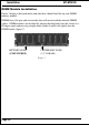
3-2. Install memory chips
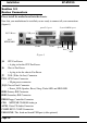
3-3. Device Connectors
3-4. External Modem Ring-in Power ON and Keyboard Power ON
Functions (KBPO)
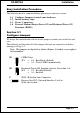
Section 3-1
Configure Jumpers
We design this motherboard with the fewest jumpers to make your install fast and
easy.
The following will describe all of the jumpers that you are required to set before
moving on to step 3-2.
Note: The jumpers as depicted as shown (Figure 1) in their correct physi-
cal orientation.
JP4 Keyboard Power-ON function (refer to the section 3-4)
JP4 = 1-2 -
= 2-3 -
Disabled(Default)
Enabled
1
3
J7 W OL (Wake On Lan) Connector
Reserved for NIC (Network Interface Card) to
Wake the System.
JP1 = 1-2 - Run Mode (Default)
= 2-3 - Clear CMOS (momentarily)
JP1 CMOS Clear
1
3