Digital Tier Shaker MANUAL NO: M1196-0050 Revision N May 23, 2002 NEW BRUNSWICK SCIENTIFIC CO., INC. BOX 4005 • 44 TALMADGE ROAD • EDISON, NJ 08818-4005 Telephone: 1-732-287-1200 • 1-800-631-5417 Fax: 732-287-4222 • Telex: 4753012 NBSCO Internet: http://www.nbsc.com • E-mail: bioinfo@nbsc.
COPYRIGHT: Copyright © 2013 Eppendorf AG, Germany. No part of this publication may be reproduced without the prior permission of the copyright owner. The company reserves the right to change information in this document without notice. Updates to information in this document reflect our commitment to continuing product development and improvement. TRADEMARKS: Eppendorf® and the eppendorf logo are registered trademarks and New Brunswick and the New Brunswick logo are trademarks of Eppendorf AG, Germany.
CAUTION! This equipment must be operated as described in this manual. If operational guidelines are not followed, equipment damage and personal injury can occur. Please read the entire Operating Manual before attempting to use this unit. Do not use this equipment in a hazardous atmosphere or with hazardous materials for which the equipment was not designed. Eppendorf is not responsible for any damage to this equipment that may result from the use of an accessory not manufactured by Eppendorf.
New Brunswick Operating Manual
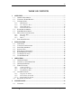
TABLE OF CONTENTS 1 OVERVIEW ..................................................................................................................... 7 1.1 GENERAL DESCRIPTION............................................................................................... 7 1.2 UNIVERSAL POWER MODULE ...................................................................................... 8 1.3 CONTROL PANEL ........................................................................................................
4.2 5 SERVICE ........................................................................................................................ 25 5.1 5.2 5.3 5.4 5.5 5.6 5.7 5.8 6 PREVENTIVE MAINTENANCE .................................................................................... 23 FUSE REPLACEMENT ................................................................................................. 25 CHANGING VOLTAGE & FREQUENCY ........................................................................
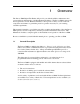
1 OVERVIEW The Innova 5000 Digital Tier Shaker will provide you with the reliable, maintenance-free operation that is characteristic of all New Brunswick shakers. The Innova 5000 is among the newest generation of New Brunswick shakers; it incorporates a variety of state-of-the-art components and features to permit the precision operation necessary for your exacting scientific experiments.
Figure 1: Front View 1.2 Universal Power Module Voltage and frequency have been set prior to shipment. Innova shakers are available in 100V, 120V, 220V and 240V, and can accommodate both 50 and 60 Hz frequencies. A voltage selector, which is incorporated in the power entry module, and a frequency selector switch are used to select the appropriate voltage and frequency. This universal system adapts to worldwide power requirements.
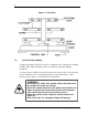
1.3 Control Panel The control panel (see Figure 2) is located on the front of the instrument. It serves as the operator interface. The keypad has four keys marked START/STOP, σ, τ and SELECT. A three-digit LED display provides numeric values as well as some letter codes. There are also four function indicator lights and four status indicator lights on the control panel. A general description of the display, user interface keys and indicators follows.
• 1.3.2 Hours remaining (timed run) User Interface Keys • START/STOP This key is used to start or stop the shaking motion. It will also activate or stop the timer when timed run is desired. • σ, τ These keys are used to adjust the setpoint of a displayed parameter up or down. They also allow the user to enter the Set mode for setpoint changes. • SELECT This key is used to change the displayed parameter. 1.3.
1.3.4 1.4 Function Indicators • RPM Revolutions per minute • HRS Time remaining • ºC Not applicable • * Not applicable Platform Assemblies The Innova 5000 can be used with wide variety of New Brunswick 32½-inch x 26¾inch (82.5 cm x 68 cm) platforms which will accept a variety of clamps for flasks, test tubes, etc. (see listing in Section 6). 1.5 Speed/Monitor Option A Speed/Monitor Option (P/N M1194-9924) is available.
1.6.2 Bearings Innova shakers employ sealed lubricated ball bearings of the highest quality. Sealed bearings minimize the generation of airborne particulates that could be disadvantageous in clean rooms or controlled environment areas. This bearing design, which requires no maintenance, has performed reliably in New Brunswick shakers for many years. 1.6.3 Motor The Innova 5000 shaker uses a brushless ball bearing DC motor.
2 2.1 INSTALLATION Unpacking Upon unpacking the unit, inspect it carefully for any apparent damage that may have occurred during transit. Immediately report any damage to the carrier and to the New Brunswick Scientific Co., Inc. Service Department. Do not discard the crate or packing material. 2.2 Voltage Configuration WARNING! Do not plug the shaker into a power source until you check the voltage setting.
Figure 3: Space Requirements The dimensions of the Innova 5000 including a platform (excluding glassware) are: Width Depth Height 2.4 62 inches 38 inches 53 inches 157 cm 96.5 cm 135 cm Installation 1. With the unit in an operating position, adjust the hollow leveling screw (see Figures 1 & 7) until the platform is level. 2. With the unit leveled, tighten the lock-nut on each leveling screw. 3. Prior to making electrical connections to the unit, set the power switch to OFF. 4.
2.5 Electrical Connections CAUTION! Before making electrical connections, be sure to follow these instructions: 1. Check the voltage and frequency selector switches on the rear of the unit to ensure that they are set to the appropriate voltage and frequency. 2. Remove the Caution label from the rear of the unit. 3. Set the circuit breaker on the front of the unit to the OFF position. ONLY THEN: 4.
Figure 4: 2- to 6-Liter Clamp Installation CLAMP MOUNTING HOLES (5) UPPER GIRDLE WITH GIRDLE TUBES PLATFORM LOWER GIRDLE WITH GIRDLE TUBES CLAMP BODY (LEGS AND BASE) Clamps for 2- to 6-liter flasks are shipped with an additional girdle to keep the flasks in place. To install 2- to 6-liter clamps, with reference to Figure 4 above: 1. Place the clamp on the platform and secure it in place with correct type of screws (refer to the clamp hardware application charts on the following page). 2.
10 to 500 ml Clamp Hardware Application Chart Part Number Qty. 10-24 x 5/8 (15.87 mm) flat Phillips (+) head screw Description S2116-3101 1 3/4" (19.05 mm) thick wood platform Application 10-24 x 5/16 (7.9 mm) flat Phillips (+) head screw S2116-3051 1 5/16" (7.9 mm) thick aluminum, phenolic and stainless steel platforms. 10-32 x 5/16 (7.
New Brunswick Operating Manual
3 3.1 OPERATION Getting Started To start the instrument, turn the power switch to the ON position. When the shaker is running, the LED display will track the speed as it accelerates to the last entered setpoint. The shaking action may be stopped or started by pressing the START/STOP key. NOTE: At the higher speed ranges, we recommend that the platforms have a 30 percent minimum load to maintain a good balance condition. 3.2 Continuous (Unlimited) Run 1. 2. 3. 4.
3.4 Timed Functions The shaker may be programmed to stop automatically after a preset time period of 0.1 hour to 99.9 hours. There must be power to the shaker in order to set the timer. However, a timed run can be initiated while the unit is either shaking or stopped. 3.4.1 Setting the Timer 1. Press the SELECT key to light HRS. 2. Press either σ or τ to enter the Set mode, then set a time period of 0.1 to 99.9 hours. 3.
The Set and Maint indicators will flash and the accumulated running time will be displayed in hundreds of hours (i.e., “02” equals 200 hours; “102” equals 10,200 hours). This display will continue for 10 seconds and then default to the previous mode readout. After 10,000 hours of operation, the Maint indicator will light. Preventive maintenance is recommended at this point. The light can be deactivated by Eppendorf service personnel.
2. Simultaneously press the σ and τ keys. The Set and Maint indicators will flash. 3. While the Set and Maint indicators are flashing, press the START/STOP key. The Mute indicator will extinguish to advise that the audible alarm is active. NOTE: The shaker may be started or stopped by pressing the START/STOP key. When starting, the unit will automatically return to the last function and speed setting. The audible alarm will sound until the speed is within 5 RPM of the setpoint.
4 4.1 MAINTENANCE Cleaning The unit may be cleaned using a cloth dampened with water or any standard household or laboratory cleaner to wipe down its outer surfaces. CAUTION! Never use abrasive or corrosive compounds to clean this instrument, as they may damage the unit and void the warranty. 4.2 Preventive Maintenance The Innova Shaker requires no routine maintenance on the part of the user. The Maint indicator light goes on at the end of 10,000 hours of use.
New Brunswick Operating Manual
5 SERVICE The following section describes basic service procedures and provides instructions to install optional features. All of these procedures must be performed by a qualified service engineer. WARNING! BEFORE any service or maintenance intervention on the instrument, the Service Engineer must turn the power switch OFF and disconnect the power cord. 5.1 Fuse Replacement The unit design incorporates a circuit breaker, which is used as an ON/OFF switch.
Figure 6: Power Entry Module 5. 6. 7. 8. Reinstall the fuse drawer in the power entry module. Set the frequency slide switch to appropriate position. Check that the proper power cord is available for the voltage selected. Plug the power cord into the power cord connection on the unit and the power source. 9. Set the ON/OFF switch to the ON position. The unit is ready for operation. 5.3 Belt Replacement When a new drive belt is needed, the Service Engineer will: (see Figure 1) 1.
5.4 Main Bearing Housing Assembly Replacement If it becomes necessary to replace the main bearing housing assembly, the Service Engineer will, with reference to Figures 7, 8 & 9 below: 1. 2. 3. 4. Set the power switch to OFF position and disconnect the power cord. Remove all platforms from the unit. Remove all 16 bolts that hold the idler housing to the base. Remove the four bolts that hold the main shaft to the the lower main housing. Figure 7: Frame End View LOWER BEARING 5.
6. 7. 8. 9. 5.5 Remove the drive belt. Remove the main drive pulley. Remove the bolts that hold the main housing to the base. Replace in reverse order. Idler Housing Repair If it becomes necessary to repair the idler assembly, the Service Engineer will follow the procedure below, with reference to Figures 7, 8 & 9. Each idler eccentric shaft may be individually removed without removing the upper shaking frame or platform assembly.
3. Remove the four bolts securing the upper portion of the idler eccentric housing to the frame. 4. Remove the four bolts holding the lower portion of the idler eccentric shaft housing to the base of the shaker. 5. With all bolts removed, the idler eccentric shaft housing may be removed by sliding it out from between the shaker base and the platform. 6. The eccentric shaft may now be removed from the idler eccentric shaft housing for repair or bearing replacement. 7.
5.6 Motor Assembly Replacement Should a new motor become necessary, the Service Engineer will: 1. Set the power switch to OFF position and disconnect the power cord. 2. Remove the drive belt. 3. Disconnect the motor power cord from the motor. 4. Remove the four bolts that hold the motor plate to the base. 5. Remove the motor from the unit. 6. Remove the motor pulley. 7. Remove the four bolts that hold the motor to the motor plate. 8. Replace the motor on the plate. 9. Replace the motor pulley. 10.
Figure 10: Upper Bearing Assembly Removal Innova 5000 M1196-0050 Operating Manual
Figure 11: Upper Shaft Assembly Removal 5.8 Speed/Monitor Option The Speed/Monitor option (#M1194-9924) offers remote monitoring, with a 0-5V analog recorder output for speed. Can be used with an external chart recorder or computer which has a data acquisition card.
6 6.1 ACCESSORIES & SERVICE PARTS Platforms All of the following platforms are available for use with the Innova 5000: Catalog Number Platform Flask Size Flasks per Platform Flasks per Shaker M1196-9447 M1196-9908 M1196-9909 M1196-9910 M1196-9900 M1196-9901 M1196-9902 M1196-9903 M1196-9904 M1196-9905 M1196-9906 M1196-9907 Universal1 10 mL 25 mL 50 mL 125 mL 250 mL 500 mL 1L 2L2 2.
6.3 Service Parts Part Number Description Qty P0380-3830 M1196-3500 M1196-3400 M1196-3100 M1196-3200 R-472 P0180-0250 B-208 M1196-9914 M1196-7001 M1196-5300 M1196-9911 Fuse .
7 SPECIFICATIONS Shaking Speed Motion Indication Setpoint & Control Accuracy 25-350 rpm 2" (50.8 mm) diameter circular orbit LED digital electric display, 1 rpm increments Digital adjustment with PI microprocessor control and instantaneous visual feedback ± 1 rpm (see NOTE below) NOTE: At 25-350 rpm, the unit will perform to specifications with up to ±10% line voltage fluctuation. Drive Eccentric counterbalanced ball bearing drive Keypad Timer Programmable shaking periods from 0.1 hour to 99.
Dimensions 62" (157 cm) Wide x 38" (96.5 cm) Deep x 53" (135 cm) High to platform surface. Construction Heavy gauge steel, phosphate coated and texture painted frame. Weight Net: Gross: 2,000 lbs. (907 kg) 2,200 lbs. (998 kg) Platform Dimensions 32.5" x 26.75" (82.
L N 21 BLK GRN N L RED A 22 VIO GRY 1 BLU 2 RED 4 3 LOAD RED WHT LINE LF001 BLU 11 12 220 CB001 10A WHT/BLK 250 120 WHT/BLK WHT 100 C MOV001 VIO F001 .20AMP VIO BR001 BLK + YEL J4-4 J4-3 WHT/BLK MOTORDRIVE PCB001 LED002 GRN RED J2-7 J2-6 J2-5 J2-4 J2-3 J3-1 J3-2 J3-3 VREF. (-) VREF.
New Brunswick Operating Manual
9 INDEX Installation, 13, 14 A K Alarm, 21 Deactivating the, 21 Reactivating the, 21 Stopping the, 21 Keypad, 9 L B Bearings, 12 Belt Replacement, 26 LED Display, 9 M C Cancelling the Timer, 20 Changing Voltage & Frequency, 25 Checking Setpoints, 19 Clamp Hardware, 16 Clamp Hardware Application Charts, 17 Clamp Installation, 15 Clamps, 33 Cleaning, 23 Continuous Run, 19 Control Panel, 9 Control Schematic, 37 D Deactivating the Alarm, 21 Dimensions, 14 Main Bearing Housing Replacement, 27 Mai
Cancelling the, 20 Setting the, 20 Total Running Time, 20 Upper Shaft Assembly Removal, 30 User Interface Keys, 10 V U Universal Power Entry Module, 25 Universal Power Module, 8 Unlimited Run, 19 New Brunswick Voltage, 13 Changing the, 25 Voltage Selection, 8 Operating Manual
Innova 5000 M1196-0050 Operating Manual
Evaluate your manual Give us your feedback. www.eppendorf.com/manualfeedback Your local distributor: www.eppendorf.com/worldwide Eppendorf AG · Hamburg · Germany · Tel: +49 40 538 01-0 Application Support E-mail: support@eppendorf.com Eppendorf North America, Inc. · USA · Tel: +1 516 334 7500 Toll free phone: +1 800 645 3050 menu option 2 E-mail: techserv@eppendorf.com www.eppendorf.