Tracer- BN Series ——MPPT Solar Charge Controller User Manual Models: Tracer1215BN/Tracer2215BN Tracer3215BN/Tracer4215BN
Important Safety Instructions Please reserve this manual for future review. This manual contains all instructions of safety, installation and operation for Maximum Power Point Tracking (MPPT) controller in Tracer-BN series ("the controller" is referred in this manual). General Safety Information Read carefully all the instructions and warnings in the manual before installation. No user serviceable component inside controller. DO NOT disassemble or attempt to repair the controller.
Contents 1 General Information ............................................................................. 1 1.1 Overview ..................................................................................... 1 1.2 Characteristics ............................................................................ 2 1.3 Accessories Instructions ........................................................... 3 1.4 Maximum Power Point Tracking Technology ......................... 3 1.5 Battery Charging Stage ...........
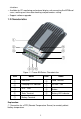
1 General Information 1.1 Overview Appreciate you for choosing MPPT solar charge controller, Tracer-BN series. Based on common negative design and advanced MPPT control algorithm, with die-cast aluminum design for heat dissipation, products in this series are artistic, economical and practical.
situations. Available for PC monitoring and external display unit connecting like MT50 and so on, realizing real-time data checking and parameters setting. Support software upgrade. 1.
② Monitor controller by PC and update controller software via RS485 (RJ45 interface). 1.3 Accessories Instructions 1. Remote Temperature Sensor (Model: RTS300R47K3.81A) Acquisition of battery temperature for undertaking temperature compensation of control parameters, the standard length of the cable is 3m (length can be customized). The RTS300R47K3.81A connects to the port (3th) on the controller. Note: Unplug the RTS, the temperature of battery will be set to a fixed value 25ºC. 2.
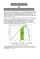
Input power (PPV)= Output power (PBat) Input voltage (VMpp) *input current (IPV) =Battery voltage (VBat) *battery current (IBat) Normally, the VMpp is always higher than V Bat, Due to the principle of conservation of energy, the IBat is always higher than I PV. The greater the discrepancy between VMpp &VBat, the greater the discrepancy between IPV& IBat.
Figure 1-3 Mutil-MPP Curve If the program works improperly after appearing Multi-MPP, the system will not work on the real max power point, which may waste most solar energy resources and seriously affect the normal operation of the system. The typical MPPT algorithm, designed by our company, can track the real MPP quickly and accurately, improve the utilization rate of the array and avoid the waste of resources. 1.
A) Bulk Charging In this stage, the battery voltage has not yet reached constant voltage (Equalize or Boost Voltage), the controller operates in constant current mode, delivering its maximum current to the batteries (MPPT Charging).
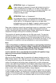
ATTENTION: Dégât sur l'équipement! L'égalisation peut augmenter la tension de la batterie jusqu'à un niveau nuisible pour les charges CC sensibles. Vérifiez que la tension d'entrée autorisées de toutes les charges disponibles sont supérieures à 11% à la tension du point d'installation de chargement d'égalisation. ATTENTION: Dégât sur l'équipement! Un chargement excessif et une précipitation de gaz peut endommager les plaques de la batterie et la formation de matières actives dessus.
2 Installation Instructions 2.1 General Installation Notes Before installation, please read through the entire installation instructions to get familiar with the installation steps. Be very careful when installing the batteries, especially flooded lead-acid battery. Please wear eye protection, and have fresh water available to wash and clean any contact with battery acid. Keep the battery away from any metal objects, which may cause short circuit of the battery.
PV modules can be calculated. The below table is for reference only. System voltage 36cell Voc<23V 48cell Voc<31V 54cell Voc<34V 60cell Voc<38V MAX. Best MAX. Best MAX. Best MAX. Best 12V 4 2 2 1 2 1 2 1 24V 6 3 4 2 4 2 3 2 System 72cell Voc<46V 96cell Voc<62V voltage MAX. Best MAX.
Model Rated Charge Current Tracer1215BN 10A Tracer2215BN 20A Tracer3215BN 30A Tracer4215BN 40A Rated Charge Power 130W/12V 260W/24V Max. PV Array Power 390W/12V 780W/24V 260W/12V 520W/24V 390W/12V 780W/24V 520W/12V 1040W/24V 780W/12V 1560W/24V 1170W/12V 2340W/24V 1560W/12V 3120W/24V Max. PV open circuit voltage 150V 138V ① ② ①At minimum operating environment temperature ②At 25℃ environment temperature 2.
Note: The wire size is only for reference. If there is a long distance between the PV array and the controller or between the controller and the battery, larger wires can be used to reduce the voltage drop and improve performance. 2.4 Mounting CAUTION: The controller requires at least 150mm of clearance above and below for proper air flow. Ventilation is highly recommended if mounted in an enclosure.
Figure 2-1 Mounting 1) Connect components to the charge controller in the sequence as shown above and pay much attention to the ―+‖ and ―-‖. Please don‘t turn on the fuse during the installation. When disconnecting the system, the order will be reserved. 2) After installation, power the controller and check the battery indicator on the controller, it will be green. If it‘s not green, please refer to chapter 4.
3 Operation 3.
Four methods to configure the controller: 1–Remote meter, MT50 (Use standard twisted net cable, model: CC-RS485-RS485-200U-MT). 2–Super parameter programmer, SPP-02(Use standard twisted net cable, model: CC-RS485-RS485-200U). One-key easily configure and apply to batch setting. 3–PC monitoring setting software ―Solar Station Monitor‖(Use USB to RS485 converter cable with model: CC-USB-RS485-150U.
3.3 Battery Type 1) Sealed (Default) 2) Gel 3) Flooded 4) User Battery Voltage Parameters (parameters is in 12V system at 25℃, please use double value in 24V.) Battery charging setting Over Voltage Disconnect Voltage Sealed Gel Flooded User 16.0V 16.0V 16.0V 9~17V Charging Limit Voltage Over Voltage Reconnect Voltage Equalize Charging Voltage 15.0V 15.0V 15.0V 9~17V 15.0V 15.0V 15.0V 9~17V 14.6V —— 14.8V 9~17V Boost Charging Voltage 14.4V 14.2V 14.
d. Under Voltage Warning Reconnect Voltage > Under Voltage Warning Voltage ≥ Discharging Limit Voltage. e. Boost Reconnect Charging voltage > Low Voltage Disconnect Voltage. CAUTION: Please refer to user guide or contact with the sales for the detail of setting operation. 3.4 Load Set Mode 1.Manual Control (default) The load can be switched by button or remote control command. 2.Light ON/Off 3.Light ON+ Timer 4.Time Control Control the load on/off time through setting real-time clock.
4 Protections, Troubleshooting and Maintenance 4.1 Protection PV Over Current The controller will limit battery charging current to the Maximum Battery Current rating. Therefore an over-sized solar array will not operate at peak power. PV Short Circuit When PV short circuit occurs, the controller will stop charging. Clear it to resume normal operation. PV Reverse Polarity Fully protection against PV reverse polarity, no damage to the controller will result.
Damaged Remote Temperature Sensor If the temperature sensor is short-circuited or damaged, the controller will be charging or discharging at the default temperature 25℃ to prevent the battery damaged from overcharging or over discharged. Controller Overheating If the temperature of the controller heat sinks exceeds 85℃, the controller will automatically start the overheating protection and recover below 75℃. High Voltage Transients PV is protected against small high voltage surge.
indicators blink. (battery indicator red blink) Load terminals no output voltage match with the controller working voltage. Please change to a suitable battery or reset the working voltage. Remove all faults and click the button to resume to work Over load or Short circuit Remove or reduce the load and press the button, the controller will resume to work after 3 seconds 4.3 Maintenance The following inspections and maintenance tasks are recommended at least two times per year for best performance.
5 Technical Specifications Electrical Parameters Item Nominal system voltage Rated charge current Rated discharge current Battery voltage range Max. PV open circuit voltage MPP voltage range Max.
Annex I Conversion Efficiency Curve Illumination Intensity: 1000W/m2 Temp: 25ºC Model: Tracer1215BN 1. Solar Module MPP Voltage(16.5V, 34V, 66V) / Nominal System Voltage(12V) 2.
Model: Tracer2215BN 1.Solar Module MPP Voltage(16.5V, 33V, 66V) / Nominal System Voltage(12V) 2.
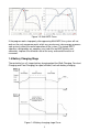
Model: Tracer3215BN 1.Solar Module MPP Voltage(16.5V, 33V, 66V) / Nominal System Voltage(12V) 12V Conversion Efficiency Curves 98 97 Conversion Efficiency(%) 16.5V 96 33V 95 94 66V 93 92 91 0 50 100 150 200 250 Charging Power(W) 300 350 400 2.
Model: Tracer4215BN 1.Solar Module MPP Voltage(16.5V, 33V, 66V) / Nominal System Voltage(12V) 2.
Annex II Dimensions Tracer1215BN Dimensions in Millimeters 25
Tracer2215BN Dimensions in Millimeters 26
Tracer3215BN Dimensions in Millimeters 27
Tracer4215BN Dimensions in Millimeters Final interpretation right of the manual belongs to EPsolar. Any changes without prior notice! Version number: V1.
BEIJING EPSOLAR TECHNOLOGY CO., LTD. Tel: +86-10-82894112 / 82894962 Fax: +86-10-82894882 E-mail:info@epsolarpv.com Website: http://www.epsolarpv.com/ http://www.epever.