
User Manual


Add:4120 Valley Blvd, Ste B, Walnut, CA 91789 Tel:1+ 626-575 7722 Wbe:www.acopower.com/
1 2
ViewStar A series solar charge controller
1. Overview
Thank you for selecting the ViewStar A series common positive solar charge
controller. The VS-A controller is a PWM charge controller with built in LCD display that
adopts the most advanced digital technique. The multiple load control modes enable it
can be widely used on solar home system, traffic signal, solar street light, solar garden
lamp, etc. The features are listed below:
3-Stage intelligent PWM charging:Bulk, Boost/Equalize, Float
Support 3 charging options: Sealed, Gel, and Flooded
LCD display design, dynamically displaying device’s operating data and working
condition
Multiple load control modes
Energy statistics function
Battery tempera
ture compensation function
Extensive Electronic protection
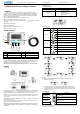
2. Product Features
①
LCD
⑤
PV Terminals
②
MENU Button
⑥
Battery Terminals
③
Mounting hole size
Φ4.5
⑦
Load Terminals
④
RTS* Port
⑧
SET Button
* Accessory:Remote Temperature Sensor (Model: RTS300R47K3.81A)
Acquisition of battery temperature for undertaking temperature compensation of control
parameters, the standard length of the cable is 3m (length can be customized). The
RTS300R47K3.81A connects to the port (4
th
) on the controller.
Note: Unplug the RTS, the temperature of battery will be set to a fixed value 25ºC.
3. Wiring
(1) Connect components to the charge controller in the sequence as shown above and
pay much attention to the “+” and “-”. Please don’t insert the fuse or turn on the breaker
during the installation. When disconnecting the system, the order will be reserved.
(2)After power on the controller, check the LCD on. Otherwise please refer to chapter
6.Always connect the battery first, in order to allow the controller to recognize the
system voltage.
(3)The battery fuse should be installed as close to battery as possible. The suggested
distance is within 150mm.
(4) The VS-A series is a positive ground
controller. Any positive connection of solar, load
or battery can be earth grounded as required.
NOTE: Please connect the inverter or other load that it has the large start current
to the battery rather than to the controller, if the inverter or other load is
necessary.
4. Operation
4.1 Button Function
Button
Function
MENU button
Browse interface
Setting parameter
SET button
Load ON/OFF
Clear error
Enter into Set Mode
Save data
4.2 LCD Display
Status Description
Item
Icon
Status
PV array
Day
Night
No charging
Charging
PV Voltage, Current ,Power
Battery
Battery capacity, In Charging
Battery voltage. current, temperature
Battery type
Load
Load ON
Load OFF
Load Voltage, Current, Load mode
Browse interface
NOTE:
1) When no operation, the interface will be automatic cycle, but the follow two
interfaces not be display.
2) Accumulative power zero clearing: Under PV power interface, press SET button
and hold on 5s then the value blink, press SET button again to clear the value.
3) Setting temperature unit: Under battery temperature interface, press SET button
and hold on 5s to switch.
Fault Indication
Status
Icon
Description
Battery over
discharged
Battery level shows empty, battery frame blink,
fault icon blink
Battery over
voltage
Battery level shows full, battery frame blink, fault
icon blink
Battery
Overheating
Battery level shows current value, battery frame
blink, fault icon blink
Load failure
Load overload
①
,Load short circuit
①When load current reaches1.02-1.05 times 1.05-1.25 times, 1.25-1.35 times and
1.35-1.5 times more than nominal value, controller will automatically turn off loads in 50s,
30s,10s and 2s respectively.
Figure 3 Connection diagram
Figure 1 Characteristic
Figure 2 RTS
②
①
③
④
⑤
⑥
⑦
⑧