
Service manual


EPSON Perfection 1240U Revision A
Operating Principles Engine Mechanism 18
2.1 Engine Mechanism
This section explains the engine function and operating principles. Engine can
be divided into Carriage Unit and Carriage Move Mechanism.
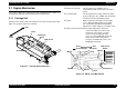
2.1.1 Carriage Unit
Carriage unit is mainly composed of CCD sensor board, Inverter board, Lamp
(light source), Mirror and Lens mechanism.
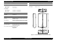
Figure 2-1. Carriage Unit Component
CCD Sensor Board: This board has Color CCD line sensor
(independent R,G,B), and controls it and drives
circuit.
Inverter Board: This board generates voltage to drive the lamp
by pressuring up to the +24VDC and converting it
from direct current to alternating current.
Lamp: White cold fluorescent Lamp is used as light
source. When the light quantity is not stable,
the scanner blinks the Operate light until the
light becomes stable and goes to stand-by mode.
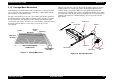
Mirror and Lens Mechanism:The light emitted to the document
reaches the CCD sensor after being
reflected on some mirrors one after
another. Not by changing the light
source to create R/G/B light component
which can be found in the previous
models, Color CCD itself creates each
R/G/B light component.
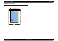
Figure 2-2. Mirror, Lens Mechanism
Rear
Front
Inverter Board
Lamp
CCD Sensor
Board
CCD Sensor
Front
Rear
Scanned image
Mirror2
Mirror4
Document
Lamp
Mirror1
Lens
Mirror3
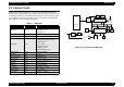
CCD Sensor
CCD Sensor
Board
B(main)
B(sub)
G(main)
G(sub)
R(main)
R(sub)