MODEL 214D-1 Batch Controller USER’S MANUAL HP-289 November 2002 107 Kitty Hawk Lane, P.O. Box 2145, Elizabeth City, NC 27906-2145 800-628-4584 252-331-1997 FAX 252-331-2886 www.hofferflow.com E-mail: info@hofferflow.
HP289
NOTICE HOFFER FLOW CONTROLS, INC. MAKES NO WARRANTY OF ANY KIND WITH REGARD TO THIS MATERIAL, INCLUDING, BUT NOT LIMITED TO, THE IMPLIED WARRANTIES OF MERCHANTABILITY AND FITNESS FOR A PARTICULAR PURPOSE. This manual has been provided as an aid in installing, connecting, calibrating, operating, and servicing this unit. Every precaution for accuracy has been taken in the preparation of this manual; however, HOFFER FLOW CONTROLS, INC.
WARRANTY HOFFER FLOW CONTROLS, INC. warrants this unit to be free of defects in workmanship and materials provided that the unit was properly selected for the service intended, properly installed, and not misused.
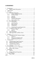
CONTENTS 1. Introduction................................................................................ 1 1.1 Model Number Designation ................................................ 2 2. Specification .............................................................................. 3 3. Operation ................................................................................... 5 3.1 Front Panel Operation ......................................................... 6 3.1.1 Setting the Batch Quantity ........
HP289
Introduction 1 1. Introduction The Model 214D-1 Batch Controller accepts pulse or frequency flow signals and automatically controls the batching of fluids via a one or two stage control valve. The instrument is extremely flexible and easy to operate, with a four key front panel operation that enables the batch quantity to be set and batches to be started or stopped.
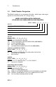
2 1.1 Introduction Model Number Designation The Model number of an instrument describes which input and output options are installed and the AC voltage rating.
Introduction 2A OPTIONS MODEL 214D-( )-( )-( )-( )-( E ) OPTION ( E ) (H) 50 W HEATER (SPECIFY 12 VDC, 115 VAC OR 220 VAC) (B) BACKLIGHTING DISPLAY (C) CONFORMAL COATING (CE) INTERFERENCE CE COMPLIANCE (CEN) CENELEC, CSA NRTL/C AND SAA APPROVAL (NTEP) WEIGHTS & MEASURES CUSTODY TRANSFER. (AVAILABLE ON (LA) OR (LR) OPTIONS ONLY) (UL) ELECTRICAL ETL (US) APPROVED TO UL508 & CSA NOTES: 1. LCD DISPLAY 6 DIGIT 0.7" (17.8MM) HIGH, NON-VOLATILE TO TEN YEARS. 2. TRANSDUCER SUPPLY 8-24 VDC @ 50 MA MAX.
Introduction 2B This page intentionally left blank.
Specification 3 2. Specification General Display: Display Update Rate: Transducer Supply: Power Requirements: Operating Temperature: Dimensions: Cutout: 6 digit LCD. 0.7" (17.8mm) high digits 0.25 seconds 8-24VDC field adjustable, 50mA maximum DC: 11.5 to 28.5 volts 130mA typical current (no options) AC: 95-135 VAC or 190-260 VAC (Set internally at factory) 0°C to 55°C standard 5.7" (144mm) wide x 2.8" (72mm) high x 7.0" (178mm) deep 5.5" (139mm) wide x 2.
4 Specification Pulse Output Pulse Width: Maximum Duty Cycle: Output: Scaling: HP289 10msec (negative going pulse) 49 pulses per second Open collector transistor will sink 100mA. The pulse output is scaled and outputs one pulse each time the accumulated total increments.
Operation 5 3. Operation The Model 214D-1 uses a low power CMOS microprocessor to perform all control functions and calculations. The instrument is fully configurable with all operating parameters and calculation constants user settable. (See Section 5 entitled "Configuration" for information on configuring.) All parameters and constants are stored in a non-volatile memory which retains data without battery backup for a minimum of 10 years. A block diagram of the instrument is shown below.
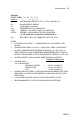
6 3.1 Operation Front Panel Operation The four key operation makes the operation of the Batch Controller very easy. 3.1.1 Setting the Batch Quantity The batch quantity is set as follows: Switch Action Press BATCH SET Display Comments Batch "Batch" is displayed for one second followed by the batch quantity last entered. The Batch Set LED lights. "1" 2345 The most significant digit flashes indicating that it can be changed. Press r "2" 2345 Pressing the DISPLAY key will increment the digit.
Operation 3.1.2 7 Starting a Batch To start the process the RUN key is pressed. The Run LED will light and the instrument will begin to totalize from zero or, if programmed to count down, the display will decrement from the batch quantity. The batcher has two control relays which are energized and deenergized as described in Section 3.2. 3.1.3 Stopping The process can be stopped at any time by pressing the STOP key.
8 Operation Accumulated Total On the next press of the DISPLAY key, the display shows ACC for one second followed by the accumulated total. The Accumulated Total cannot be reset during normal operation. 3.1.6 Limit on Batch Size To prevent accidental entry of large batch quantities, a maximum batch limit can be set during configuration. The operator is then prevented from entering a batch quantity which exceeds this predetermined value.
Operation 3.2 9 Batch Operations The Batch Control functions can be configured to operate in one of two ways. 1. At the end of the batch, the STOP key must be pressed to reset the Batch Total. (This must be done before another batch can be started.
10 Operation 2. If Automatic Reset is configured on, a new batch is commenced each time the RUN key is pressed. The Batch Controller can be configured to either count up from zero on each batch or to count down from the preset batch quantity.
Operation 3.2.1 11 Control Relays The two control relays can be set up to control a single valve or a dual valve with slow-stop and/or slow-start. Alternatively, the second relay can be used to control a pump. The relay operation is shown on the previous two pages. A time delay between the Batch Start and the time when Relay 2 energizes can be set to provide a soft start up. The delay can range from 0 (no delay) to 79 minutes and 59 seconds. A Prestop quantity (i.e.
12 Operation 3.2.2 Signal Timeout The Signal Timeout period defines a time interval which is used to detect if the flow has stopped. If there is no signal input for a time greater than the Signal Timeout period the flow is deemed to have stopped. The Signal Timeout period has two functions: • To detect the loss of signal during a batch when the relays are energized. In this case, the Batcher will enter a Flow Alarm condition and de-energize the relays.
Operation 3.2.3 13 End-of-Batch The End-of-Batch is defined as being when the Batch Quantity is reached, the flow has stopped, and the Signal Timeout period has expired. If the Signal Timeout is set to zero, the End-of-Batch is defined as being when the Batch Quantity is reached, regardless of whether the flow has stopped.
14 Operation 3.2.4 Auto Restart The Batch Controller can be configured to continually repeat the batch process. This mode of operation is selected during the configuration process. The process is started by pressing the RUN key whereby the normal batch operation is commenced. After reaching the End-of-Batch (see Section 3.2.3), the Batch Controller will then wait for a preprogrammed period before automatically resetting and starting the batch process again.
Operation 3.2.5 15 Automatic Overrun Compensation The Batch Controller can be configured to automatically compensate for any overrun at the end of a batch. Typically, this is due to the slowness of a valve to close or a pump to stop pumping on receiving a signal from the Batch Controller. The result is that the batch quantity will always read higher than the batch quantity set.
16 3.3 3.3.1 Operation Calculation of Rate and Total Frequency Input The flowrate, R, is calculated as follows: R= fxH S where f is the input frequency in Hz. H is the timebase of rate and is 1 for seconds, 60 for minutes,3600 for hours, and 86,400 for days. S is the Scaling Factor. The Scaling Factor, S, is equal to the K-factor of the flowmeter expressed in pulses per unit volume.
Operation 3.3.2 17 Filtering Frequency fluctuations caused by pulsating flow through a flowmeter, often makes the Rate impossible to read with any precision. The Batch Controller has a digital filter which will average out these fluctuations and enable the Rate to be read to four digit accuracy. The degree of filtering is fully configurable which means that highly accurate and stable readings can be obtained without excessive lag.
18 Operation A 90% 99% 1 0 0 2 1 2 4 2 4 6 3 6 10 5 11 15 8 17 20 11 22 25 14 28 35 20 40 45 25 51 60 34 69 75 43 86 90 52 103 99 57 113 Table 1 - Response to a step Input (in seconds). Note: if A is set to 1, there is NO filtering of the input signal.
Operation 3.4 19 Total Conversion The Total Conversion feature enables the rate to be displayed in one engineering unit (e.g., gallons/minute) and the totals to be displayed in another engineering unit (e.g., barrels). The Scaling Factor is always set in the unit relating to Rate and the Total Conversion constant is a division factor which can be used to convert the totals to the different unit. The Total Conversion factor affects the net, accumulated, and gross totals and is limited between 0.
20 3.5 Operation The Output Pulse and Flow Alarm An OUTPUT PULSE is available on terminal 10 for driving remote counters and produces a pulse each time the Accumulated Total increments by one digit. For example, if the Accumulated Total has a resolution of 0.01 gallons, a pulse is produced each 0.01 gallons. The pulse is a current sinking pulse of approximately 10msec produced by an open collector transistor and can sink up to 100mA.
Operation 21 Connection of Output Pulse/Flow Alarm is as follows: Driving an External Relay or Impulse Counter Driving a Logic Input such as a PLC or Electronic Counter HP289
22 Options 4. Options 4.1 The RS232/422/485 Interface Option With this option installed, the circuits for both the RS232 and RS422/485 interfaces are provided as standard. They can be used to interface to both printers and computers. A number of standard printer protocols are built into the instrument. 4.1.1 Hardware The following diagram provides an overview of the RS232/RS422/RS485 communications hardware.
Options 23 4.1.2 Multipoint Communication Multipoint Communication is a system whereby a number of instruments can be addressed over a dual twisted pair interface. Up to 32 instruments can be connected to a common bus using the RS422 and RS485 interfaces as shown below. To convert the RS422 interface to an RS485 interface, the RS422 (-) Data In Terminal must be connected to the RS422 (-) Data Out Terminal and the RS422 (+) Data In Terminal must be connected to the RS422 (+) Data Out Terminal.
24 Options Figure 2 RS485 Interface HP289
Options 25 4.1.3 Communication Protocol The RS232/422/485 option has a real time clock and enables the time and date to be set and printed on tickets. The date format can be European (days/months/years) or USA (months/days/years) while the time is on a 24 hour clock. Note that the clock will only retain its time for 3 days (minimum) if there is no power connected to the instrument. After this period, the clock may need to be reset.
26 Options input is usually connected to the "Data Buffer Full" output from the printer. If the printer buffer is large enough to handle the message output from the instrument, then this input need not be used and should be left unconnected. Computer The instrument receives and transmits messages in ASCII with all command strings to the instrument terminated by a carriage return. While replies from the instrument are terminated with a carriage return and a line feed.
Configuration 27 5. Configuration The Configuration process enables the Setup Parameters to be configured, as well as enabling the input signals to be checked. The configuration process can be entered in one of two ways: 1 2 By connecting a wire link (or switch) to the rear terminal strip across terminals 1 and 2 By pressing the TOTAL key and while holding, pressing the RESET key. Both keys must then be held for approximately 6 seconds.
28 Configuration The user can toggle between these modes using the DISPLAY key and by using the STOP key select the appropriate mode. To exit Configuration, step through the Setup program, Batch program, or Test program until the end and press the STOP key when End is displayed (ensure the configuration link is removed).
Configuration 5.1 29 Configuring the Setup Parameters Step Display 1 CAL BATCH OPTION TEST END Description Text Ref Setup Program Parameters Set Batch Parameters Options (if installed) Check Input Signals Exit to normal operation 5.2 5.3 5.4 The following steps are displayed when CAL is selected. 2 3 4 5 6 7 8 RESTOT Reset all totals to zero. To clear all totals (resettable and accumulated) press the BATCH SET key once. SCALE Scaling Factor.
30 Configuration Step Display 9 A.dPt 10 HP289 Description Number of decimal points with which the Accumulated (non resettable) total is displayed between 0 to 00. ACCESS Enable access to configuration routine via the front keyboard only. Front Enable access via front keyboard. No Acc Disable access via front keyboard.
Configuration 5.2 31 Entering the Batch Parameters Step Display 1 BATCH OPTION TEST END CAL Description Text Ref Set Batch Parameters Options (if installed) Check Input Signals Exit to normal operation Setup Program Parameters 5.3 5.4 5.1 The following steps are displayed when BATCH is selected. 2 3 4 5 6 7 8 BATCH L Maximum Batch Size which can be entered. xxxxxx Set to 0 if no limit on batch size. AUTO S Automatic restart feature.
32 Configuration Step 9 10 HP289 Display Description OUT 30 Output on Terminal 30. PC “Pump Control”. EOB End of Batch output AUTO R Auto Reset (not displayed if Auto Restart is programmed - Step 3 above). Off Batch Total must be manually reset before starting the next batch. On The Batch can be automatically reset and started by pressing only the RUN key. Text Ref 3.
Configuration 5.3 33 Configuring the Options Step Display 1 OPTION TEST END CAL BATCH Description Options (if installed) Check Input Signals Exit to normal operation Setup Program Parameters Set Batch Parameters Text Ref 5.4 5.1 5.2 If the RS232/422/485 option is installed, the following will be displayed: 2 3 4 5 6 7 8 9 10 DF Eur USA Date xx:xx:xx HOUR xx:xx BAUD xxxx DATA 7 8 PARITY NP OP EP SIGNAL rs232 rs422 ID NO 0 1 - 99 PTYPE xx 00 01 02 03 Date Format. European (i.e.
34 Step Configuration Display Description 04 05 Contrec Model 632-2 Printer Syntest SP-210 Printer 20 Computer Text Ref If a Printer Protocol is selected, the following message is displayed: 11 UNIT xx Units of measurement printed. 00 01 02 03 04 05 06 07 None Liters (Ltrs). Gallons (Gals) Barrels (bbls) Pounds (lbs) Grams (gms) Kilograms (kgs) Tons (tons) If a Computer Protocol is selected, the following message is displayed: 11 HP289 ECHO On Off ECHO Commands.
Configuration 5.4 35 Checking the Input Signal Step Display 1 TEST END CAL BATCH OPTION Description Text Ref Check Input Signals Exit to normal operation Setup Program Parameters Set Batch Parameters Options (if installed) 5.1 5.2 5.3 The following steps are displayed when TEST is selected. 2 3 Sr x.xx Freq xxxx.x Software revision number. Displayed for 1 second followed by the actual frequency. Frequency in Hz.
36 Input Circuits 6. Input Circuits This section covers the connection of flowmeter signals for the Model 214D Series Batch Controllers. The 214D Series has a regulated power supply output which can be used to power sensors. A trimpot on the rear of the instrument allows the voltage to be adjusted in the range of 8-24 Volts and the output can supply a maximum of 50mA. 6.
Input Circuits 37 Switch Settings The following switch settings are recommended for different input signal types. Input Signal Type Input Terminals Switch Settings CH1 (+) (-) 9 8 off off off off on off off off 9 8 off off off off on off on off 11 9 off off on on on off off off 9 8 off off off off on off on 9 8 off on off off off off off off 9 8 on on off off off off off off a. Logic Signal, 1 2 3 4 5 6 7 8 CMOS, Pulse b. Open Collector or Reed switch c.
38 Input Circuits The Frequency Input Circuit HP289
Input Circuits 1. MAG Coil 2. Redi-Pulse, CMOS or Pulse 3.
40 Input Circuits 4. Squarewave, CMOS or Pulse 5. Open-Collector 6.
Input Circuits 6.2 41 Remote Key Switches Remote push-buttons can be connected to the Model 214D-1 to duplicate the keys on the front panel.
42 Installation 7. Installation 7.1 General Terminal designations for the Model 214D Batch Controller are given on the following pages. The cutout hole in the panel should be 5.5" (139mm) wide x 2.6" (67mm) high. Two side clips are supplied to secure the instrument into the panel. A case grounding point is provided via a ground lug on the side of the case. Note that this grounding point is for the case only and there is complete electrical isolation between this point and all electronic circuits.
Installation 43 should be as short as possible and connected to the grounding lug on the side of the case. In order to comply with the requirements for Electromagnetic Compatibility as per EMC-Directive 89/336/EEC of the Council of European Community, this wiring practice is mandatory. Although it is also possible to connect shields to the signal ground (terminal 2) this practice is not in accordance with EMC directives.
44 7.
Trouble Shooting 45 8. Trouble Shooting Batcher does not reset The Signal Timeout has been set to an excessively long period and has not timed out at the end of the last batch. Batch will not start or relay 1 will not close Ensure that the instrument has not timed out as controlled by the Signal Timeout and that a Flow Alarm condition does not prevail. Pressing the Stop switch will cancel this condition. Check for a fault on the flow input before restarting.
46 Trouble Shooting Scaling Factor should be set to 1 and the Resolution to whole numbers. Counting erratically This can be caused by two factors: § § Setting the input circuit incorrectly Lack of shielding on the input wiring Ensure that the input selection DIP switch is correctly set for the flowmeter attached. Shield the input signal with the shield connected at the batch controller only. Instrument acting erratically Erratic operation can be the result of severe electrical interference.
Trouble Shooting 47 8.1 Error Codes The instrument has extensive self test facilities and will display an error code if it detects an invalid condition. If the instrument displays an error code other than those listed below, please contact the factory. Error codes are displayed as "Err ##" and a list of the commonly encountered codes are given below: Input Errors 11 Invalid input configuration programmed. 13 Signal Timeout (see Section 3.2.2). 14 Communications Input error (RS232/422/485 interface).
48 Index Index A E L AC Voltage, 42 access, 30 Auto Reset, 7 Auto Restart, 14 Automatic Overrun Compensation, 15 electrical noise, 43 End of Batch, 13 Error Codes, 47 Limit on Batch, 8 Logic Signals, 36 Loss of Signal, 12 F M Filtering, 17 Flow Alarm, 12 Flowrate calculation, 16 Frequency Input, 16 Frequency Range, 3 Front Panel, 6 Maximum Input Voltage, 37 Model Number, 2 Multipoint Communicatio n, 23 B Batch Limit, 8 Batch Set, 6 Baud rate, 25, 33 C clock, 25 Communication Protocol, 25 commun
Index Regulated Voltage, 42 Remote Pushbuttons, 41 Resetting, 7 Response, 18 RS232/422/485 Interface, 22 Run Key, 6 S Scaling Factor, 16 Scaling Range, 3 self test, 47 Setting the Batch, 6 Setup Parameters, 27 Signal Timeout, 12 Slow Start, 11 Slow Stop, 11 Snubbers, 43 Specification, 3 Starting, 7 Stop Key, 11 Stopping, 7 Supply Output, 42 Switch Settings, 37 Switching Threshold, 37 49 T Terminal Wiring Designations, 44 Tickets, 25 time, 25 Time Delay, 11 Timebase, 29 Total Conversion, 19 Transducer