Color Image Scanner EPSON Perfection 610 ® SESC990016
EPSON Perfection 610 Rev. B Notice: All rights reserved. No part of this manual may be reproduced, stored in a retrieval system, or transmitted in any form or by any means, electronic, mechanical, photocopying, recording, or otherwise, without the prior written permission of SEIKO EPSON CORPORATION. The contents of this manual are subject to change without notice. All effort have been made to ensure the accuracy of the contents of this manual.
EPSON Perfection 610 Rev. B PRECAUTIONS Precautionary notations throughout the text are categorized relative to 1)Personal injury and 2) damage to equipment. DANGER WARNING Signals a precaution which, if ignored, could result in serious or fatal personal injury. Great caution should be exercised in performing procedures preceded by DANGER Headings. Signals a precaution which, if ignored, could result in damage to equipment.
EPSON Perfection 610 Rev. B PREFACE This manual describes basic functions, theory of electrical and mechanical operations, maintenance and repair procedures of EPSON Perfection 610. The instructions and procedures included herein are intended for the experienced repair technicians, and attention should be given to the precautions on the preceding page. The chapters are organized as follows: CHAPTER 1. PRODUCT DESCRIPTIONS Provides a general overview and specifications of the product. CHAPTER 2.
EPSON Perfection 610 Rev. B Revision Status Revision Issued Date Description A June 16, 1999 First Release B August 2, 1999 Parts list and exploded digrams have been added to Appendix.
EPSON Perfection 610 Rev. B Contents Product Description Features ......................................................................................................... 8 Specifications ................................................................................................. 8 Interface Specifications ................................................................................ 11 USB Specifications..................................................................................
PRODUCT DESCRIPTION
EPSON Perfection 610 Revision B 1.1 Features 1.2 Specifications The major features of the EPSON color image scanner Perfection 610 are as follows.
EPSON Perfection 610 Revision B Number of hubs: This device must be in the Tier 1 or 2 with a recommended USB cable. (Tier 1: Host - this device, Tier 2: Host - Hub this device) Light source: White cold cathode fluorescent lamp Option: None Operate switch: None LED indicator: None Start button: Ease of use with Page Manager Scanning time: Color A4, Pentium 300MHz 300 dpi: 60 seconds 600 dpi: 280 seconds EMC: FCC Part15 Subpart B Class B CSA C108.
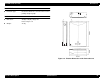
EPSON Perfection 610 Revision B DOCUMENT Reflective type: Documents which has a smooth surface such as printing and photograph. DIMENSION Dimension: 287(W) x 425(D) x 88(H) mm Refer to Figure 1-2. Weight: 4.5 Kg Figure 1-2.
EPSON Perfection 610 Revision B 1.3 Interface Specifications This section provides specifications of the USB, the only interface supported by the Perfection 610. Table 1-2. Configuration Element 1.3.1 USB Specifications Device • • • • • • • Class: Vendor specific Subclass: Vendor specific Protocol: Vendor specific Maximum packet size for endpoint 0: 8byte Vendor ID: 0x04B8 (Seiko EPSON Corp.
EPSON Perfection 610 Revision B 1.4 Control Codes 1.5 Lamp Descriptions The command level of this scanner is ESC/I-D1. The commands supported are shown in the table below. Since this scanner does not have any LED indicator, it shows the various conditions by turning on/off or blinking the lamp. Conditions indicated by the lamp are as listed below: Table 1-3.
EPSON Perfection 610 Revision B 1.6 Error Indications Refer to Section 1.5 for the error indications. Indicator: The lamp starts blinking. (The lamp goes off after 30 minutes.) The lamp does not light up when it has blown. Remedy: (After the cause of the error is removed) Turn the scanner off and then back on. Connect the USB cable again. Receiving of ESC@ Acceptable command: [ESC F, ESC f, ESC @] COMMAND ERROR Cause: Undefined command is detected.
EPSON Perfection 610 Revision B 1.
CHAPTER 2 OPERATING PRINCIPLES
EPSON Perfection 610 Rev. B 2.1 Engine Mechanism This section explains the engine functions and operating principles of the EPSON Perfection 610. The engine mechanism has the two major parts; the carriage unit (=scanning head) and the carriage move mechanism. 2.1.
EPSON Perfection 610 Rev. B 2.1.2 Carriage Drive Mechanism A line-type color CCD sensor, which is included in the carriage unit, scans one line at a time in the main scan direction (parallel to the carriage unit). To scan next lines in the sub-scan direction after the first line, the scanner moves the carriage unit with the CCD sensor in it along the sub-scan direction. The scanned data is sent to the control board.
EPSON Perfection 610 Rev. B 2.1.3 Power Supply Circuit Power supply circuit board in this scanner generates direct current necessary for driving the controller board and scanner engine. See Table 2-1 and Table 2-2 for the power supply circuit board specifications and the protection circuits for each output voltage/current, respectively. Figure 2-5 shows the power supply circuit diagram. Table 2-1. Power Supply Circuit Board Specifications for Each Destination Specification Unit Part No.
EPSON Perfection 610 F u ll W a v e R e c tifie r C ir c u it Rev.
EPSON Perfection 610 Rev. B 2.1.4 Control Circuit The CPU (IC11) of this scanner is a one-tip 16-bit bus CPU operating at 20MHz. ASIC (IC7) manages input signal correction, image processing, and controlling the CCD sensor board and USB interface. Table 2-3 shows the major IC functions. R e g u la to r (IC 9 ) 3 .3 V D C R e g u la to r (IC 1 2 ) 5 V D C Table 2-3.
TROUBLESHOOTING
EPSON Perfection 610 Revision B 3.1 Overview Table 3-1. Errors Detected by the Self-Diagnostic Function This chapter describes troubleshooting procedures for this scanner. Lamp Condition Command Error Cause: Undefined command Disposition: The scanner ignores the wrong command and parameters, and returns NACK and waits for the next command and parameters. Remedy: The scanner clears the error when it receives a correct command and parameters. Blinking (Goes off after 30 minutes.
EPSON Perfection 610 Revision B 3.3 Troubleshooting Table 3-4. The carriage unit does not operate. Cause This section describes how to troubleshoot problems according to exhibited phenomenons. See Table 3-2 that enables you to find the defective part to the unit level. Then refer to the corresponding table for checkpoints and solutions. Table 3-2. Problems and Corresponding Tables to Refer to Phenomenon Problem The PS (Power Supply) board is defective. The carriage drive mechanism is defective.
EPSON Perfection 610 Revision B Table 3-7. Image is not read clearly. Table 3-5. The carriage unit operates but the error is indicated. Cause The CR home position sensor is defective. Step Checkpoints 1 Check the signal levels between the collector (+) and emitter (-) of PC1. The signal level should change depending on the condition below: • HIGH (4.5V) = Light is blocked in PC1. • LOW (0.3V) = Light passes in PC1.
CHAPTER 4 ASSEMBLY AND DISASSEMBLY
EPSON Perfection 610 Revision B 4.1 Overview 4.1.2 Tools Use the tools specified in Table 1-1. This chapter describes procedures for disassembling the EPSON Perfection 610. Unless otherwise specified, the scanner can be disassembled by reversing the disassembly procedures. Table 4-1. Tools Names Availability Phillips screw driver (#2) Standard screw driver 4.1.
EPSON Perfection 610 Revision B 4.2 Disassembly Procedures 4.2.1 Releasing the Carriage Lock 1. Using a standard screw driver, release the Carriage Lock located at the left side of the scanner body. : Released C A U T IO N : Locked When locking the carriage for transporting the scanner, make sure the carriage is at the home position. Figure 4-2.
EPSON Perfection 610 Revision B 4.2.2 Document Cover Removal 1. Open the Document Cover. 2. Holding the Document Cover by the edges, release the two hooks by pushing the cover to the rear as shown in Figure 4-4. Document Cover Hooks Figure 4-3. Document Cover Removal (1) Assembly and Disassembly Figure 4-4.
EPSON Perfection 610 Revision B 4.2.3 Upper Housing Removal 1. Release the Carriage Lock. (See Section 4.2.1.) 2. Remove the Document Cover. (See Section 4.2.2.) Three Hooks on the Front 3. Remove the two screws (gold, CBS, M3x6) at the back of the scanner body. 4. Lifting up the rear end of the Upper Housing, release the three hooks at the front end, and then remove the Upper Housing toward the front. Figure 4-6. Upper Housing Removal (2) CBS Screws (M3x6) Figure 4-5.
EPSON Perfection 610 Revision B 4.2.4 Inverter Lamp / Inverter Board Removal 1. Release the Carriage Lock. (See Section 4.2.1.) 2. Remove the Document Cover. (See Section 4.2.2.) 3. Remove the Upper Housing. (See Section 4.2.3.) 4. Remove the two screws (CCP, M3x8) on the Carriage Unit. (See Figure 4-8.) 5. Using a standard screw driver, lift up the carriage cover in the Carriage Unit, and then move it to the front to remove it. (See Figure 4-9.) CCP Screws (M3x8) Figure 4-8.
EPSON Perfection 610 Revision B 6. Disconnect the connector for the Inverter Lamp from the Inverter Board. 7. Remove the black screw and disconnect the 2-pin connector for the CCD sensor, and then remove the Inverter Board. Connector Inverter Board 8. Remove the Inverter Lamp from the carriage cover. C H E C K P O IN T When installing the Inverter Lamp, locate the connectors correctly as shown in the following figures. Black Screw Connector (2-pin) Figure 4-10.
EPSON Perfection 610 Revision B 4.2.5 Carriage Unit Removal 1. Release the Carriage Lock. (See Section 4.2.1.) 2. Remove the Document Cover. (See Section 4.2.2.) 3. Remove the Upper Housing. (See Section 4.2.3.) 4. Using a standard screw driver, remove the timing belt clamp securing the timing belt and the carriage. Timing Belt Clamp Figure 4-12.
EPSON Perfection 610 Revision B 5. Remove the hexagon nut at the rear end of the carriage guide shaft. 6. Remove the tension spring and the screw (gold, CBS, M3x4) securing the driven pulley assembly. Tension Spring Figure 4-14. Driven Pulley Assembly Removal (1) Hexagon Nut Figure 4-13. Hexagon Nut Removal CBS Screw (M3x4) Figure 4-15.
EPSON Perfection 610 Revision B 7. Release the timing belt from the driven pulley. 8. Remove the driven pulley assembly by pushing it in the direction indicated with the arrow. (See Figure 4-17.) 9. Remove the CR shaft from the Carriage Unit. 7. Figure 4-17. Driven Pulley Assembly Removal (3) Driven Pulley Timing Belt Carriage Unit Figure 4-16. Timing Belt Removal CR Shaft Figure 4-18.
EPSON Perfection 610 Revision B 10. Inserting a standard screw driver from the back, remove the FFC metal clamp. 11. Release the FFC (white) from the connector and the two guide tabs in the Carriage Unit, and then remove the Carriage Unit. Carriage Unit Carriage Unit FFC Metal Clamp Figure 4-20. Carriage Unit FFC Cable Guide Tabs Connector Figure 4-19.
EPSON Perfection 610 Revision B 4.2.6 Carriage Motor / Timing Belt Removal 1. Release the Carriage Lock. (See Section 4.2.1.) 2. Remove the Document Cover. (See Section 4.2.2.) CR Motor Unit 3. Remove the Upper Housing. (See Section 4.2.3.) 4. Remove the Carriage Unit. (See Section 4.2.5.) Connector 5. Remove the two screws (CBS, M3x4) securing the FFC fixing plate, and then remove the FFC fixing plate. 6.
EPSON Perfection 610 Revision B 9. Follow the steps below to remove the Timing Belt from the CR Motor Unit. 1) Remove the E-ring. 2) Remove the transmission gear. 3) Disengage the timing belt from the drive pulley. E-ring Timing Belt Transmission Gear Figure 4-24. Timing Belt Removal Timing Belt Drive Pulley Transmission Gear E-ring Figure 4-25.
EPSON Perfection 610 Revision B 4.2.7 Main Board Removal 6. Hooks 1. Release the Carriage Lock. (See Section 4.2.1.) 2. Remove the Document Cover. (See Section 4.2.2.) 3. Remove the Upper Housing. (See Section 4.2.3.) 6. Main Board Cover 6. CBS Screws (M3x6) 4. Slide the Carriage Unit slowly until you see the whole main board cover. 5. CBS Screws (M3x4) 6. CBS Screw (M3x4) 5. Remove the two screws (CBS, M3x4) securing the FFC fixing plate, and then remove the FFC fixing plate. 4. Carriage Unit 6.
EPSON Perfection 610 Revision B 7. Remove the screw (CP, M3x5) near the I/F connector and the one (CBS, M3x5) securing the Main Board. Carriage FFC Connector CN4 (Power Supply Unit) 8. Disconnect the following cables from the corresponding connectors; CR Motor - CN6, carriage FFC, Power Supply Board - CN4. 9. Remove the Main Board. CN6 (CR Motor) CBS Screw (M3x5) Figure 4-28. Main Board Removal (3) CP Screw (M3x5) Figure 4-27. Main Board Removal (2) Figure 4-29.
EPSON Perfection 610 Revision B 4.2.8 Panel Board Removal 1. Release the Carriage Lock. (See Section 4.2.1.) 2. Remove the Document Cover. (See Section 4.2.2.) 3. Remove the Upper Housing. (See Section 4.2.3.) 4. Remove the screw (gold, CBS, M3x4). C H E C K P O IN T In the following steps, manually move the carriage back and forth slowly if necessary. Connector 5. Disconnect the locking connector (pull and release) for the Panel Board from the Power Supply Board, and then remove the Panel Board.
EPSON Perfection 610 Revision B 4.2.9 Power Supply Board Removal 1. Release the Carriage Lock. (See Section 4.2.1.) 2. Remove the Document Cover. (See Section 4.2.2.) 3. Remove the Upper Housing. (See Section 4.2.3.) C A U T IO N In the following steps, manually move the carriage back and forth slowly if necessary. AC Cable 4. Release the locking connector (pull and release) for the Panel Board, and then disconnect the cable from the Power Supply Board. (Refer to Figure 4-30.
EPSON Perfection 610 Revision B 6. Remove the two screws (gold, CBS, M3x4) securing the shield plate, and then remove it toward the inside. 7. Disconnect the cable from the locking connector (push and release), remove the five screws (gold, CBS, M3x4), and then remove the Power Supply Board from the shield plate. CBS Screws (M3x4) Shield Plate Figure 4-34. Power Supply Board Figure 4-32. Power Supply Board Removal (1) CBS Screws (M3x4) Connector CBS Screws (M3x4) Figure 4-33.
ADJUSTMENT
EPSON Perfection 610 Revision B This scanner needs no adjustment at the level of the service, including part replacement, specified in Chapter 4 “Disassembly and Assembly”.
CHAPTER 6 MAINTENANCE
EPSON Perfection 610 Rev. B 6.1 Overview Table 6-2. Lubrication Points Figure This chapter provides information necessary to keep the scanner function in optimum condition constantly and to prevent troubles. Lubrication Points Lubrication Table 6-1 Transmission gear shaft of the CR motor and drive pulley shaft. G-26 (1x3 mm) for each Figure 6-1 Driven pulley shaft G-26 (1x3 mm) 6.1.1 Cleaning Perform cleaning when stain is noticeable.
CHAPTER 7 APPENDIX
EPSON Perfection 610 Rev. B 7.1 Overview 7.1.2 Connector Assignment This section provides useful information for servicing this scanner. Table 7-1. Connector Summary- B103MAIN Connector Number 7.1.
EPSON Perfection 610 Rev. B Table 7-2. Main Board - CN4 Table 7-5. Power Supply Board - CN1 Pin No. Signal I/O Pin No. Signal 1, 2, 6, 7, 11, 12 GND - 1 AC (H) I/O I 3 +12V I 2 AC (L) I 4, 5 +5V I 8, 9 +24V I 10 PM-SW I Table 7-6. Power Supply Board - CN102 Table 7-3. Main Board - CN5 Pin No. Signal I/O 1 NC - 2 NC - 3 Push-SW I Pin No.
EPSON Perfection 610 Rev. B 7.2 Parts List and Explode Diagrams Table 7-9. Parts List Ref. # Appendix Description Ref. # Description Ref. # Description 100 FRAME,BASE 122 LOGO PLATE;E 146 MOTOR ASSY.,CR 101 HOUSING ASSY.,UPPER;ASP 123 EXTENSION SPRING,18.4 147 C.B.S. SCREW 102 KNOB,MOUNT,CARRIAGE 124 FOOT 148 C.B.
145 300 See P.2 112 140 104 500 400 111 122 145 140 145 330 145 147 139 103 128 180 145 183 141 145 138 135 141 146 105 145 133 147 107 101 136 137 102 106 145 119 141 132 130 131 108 147 114 115 116 144 145 117 200 119 149 143 100 109 134 149 181 145 113 110 123 118 124 120 127 401 148 127 127 126 127 331 (for 220/240V) 144 124 125 148 115 121 126 127 GT-6600/PERFECTION 610 No.1 Rev.
503 508 509 511 508 504 508 502 507 505 (NOT ASP.) 506 510 GT-6600/PERFECTION 610 No.2 Rev.