EPSON Endeavor™ ® Setup Guide Quick steps for setting up your system
FCC COMPLIANCE STATEMENT FOR AMERICAN USERS This equipment has been tested and found to comply with the limits for a class B digital device, pursuant to Part 15 of the FCC Rules. These limits are designed to provide reasonable protection against harmful interference in a residential installation. This equipment generates, uses, and can radiate radio frequency energy and, if not installed and used in accordance with the instructions, may cause harmful interference to radio and television reception.
EPSON ® Setup Guide @ This manual is printed on recycled paper and is 100% recyclable.
IMPORTANT NOTICE DISCLAIMER OF WARRANTY Epson America makes no representations or warranties, either express or implied, by or with respect to anything in this manual, and shall not be liable for any implied warranties of merchantability and fitness for a particular purpose or for any indirect, special, or consequential damages. Some states do not allow the exclusion of incidental or consequential damages, so this exclusion may not apply to you. COPYRIGHT NOTICE All rights reserved.
Important Safety Instructions 1. Read all of these instructions and save them for later reference. 2. Follow all warnings and instructions marked on the computer. 3. Unplug the computer from the wall outlet before cleaning. Use a damp cloth for cleaning; do not use liquid or aerosol cleaners. 4. Do not spill liquid of any kind on the computer. 5. DO not place the computer on an unstable cart, stand, or table. 6.
10. Do not allow the computer’s power cord to become damaged or frayed. 11. If you use an extension cord with the computer, make sure the total of the ampere ratings of the devices plugged into the extension cord does not exceed the ampere rating for the extension cord. Also, make sure the total of all products plugged into the wall outlet does not exceed 15 amperes. 12. Do not insert objects of any kind into this product through the cabinet slots. 13.
Instructions Importantes de Skuriti! 1. Lire completement les instructions qui suivant et les conserver pour references futures. 2. Bien suivre tous les avertissements et les instructions indiques sur l’ordinateur. 3. Debrancher l’ordinateur de toute sortie murale avant le nettoyage. Utiliser un chiffon humide; ne jamais utiliser un nettoyeur liquide ou une bonbonne aerosol. 4. Ne jamais renverser un liquide d’aucune sorte sur l’ordinateur. 5.
vi
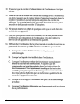
Contents Introduction Chapter 1 Setting Up Your System 1 Choosing a Location . . . . . . . . . . . . . . . . . . . . . . . . 1-2 2 Removing the Protective Card . . . . . . . . . . . . . . . . . . 1-3 3 Connecting a Monitor . . . . . . . . . . . . . . . . . . . . . . 1-4 4 Connecting a Printer or Other Device . . . . . . . . . . . . . . 1-7 Using the Parallel Port . . . . . . . . . . . . . . . . . . . . . 1-7 Using the Serial Ports . . . . . . . . . . . . . . . . . . . . . 1-9 5 Connecting the Keyboard .
Checking System Memory . . . . . . . . . . . Setting the Booting Sequence . . . . . . . . . Setting the Virus Warning . . . . . . . . . . . Setting the NumLock Boot Status . . . . . . . Setting the Bus Control Options . . . . . . . . Setting the I/O Control Options . . . . . . . . Setting the Cache/DRAM Control Options . Saving Your Settings and Exiting SETUP . . Post-SETUP Procedures . . . . . . . . . . . . Appendix A . . . . . . . . . . . . . . . . . . ... ... . . . . . . . . . . . . . . . . . . . . .
Introduction This manual explains how to set up your Epson@ computer. Chapter 1 provides simple instructions for setting up your system and connecting peripheral devices such as the monitor, mouse, and printer. Chapter 2 describes how to run the SETUP program to define your computer’s configuration. Do this before you use your computer. If you change the configuration later, you will need to run it again. After you set up your system and run SETUP, you can install your operating system and software.
Chapter 1 Setting Up Your System To set up your computer, follow the eight steps in this chapter. You may want to open this manual’s back cover foldout so you can refer to the illustrations identifying the different parts.
1 Choosing a Location When selecting a place to set up your system, choose a safe, convenient location that provides the following: A flat, hard surface. Surfaces like beds and carpets attract static electricity, which can erase data on your disks, damage the computer’s circuitry, and prevent proper ventilation. Good air circulation. Leave several inches of space around the computer so air can move freely. Moderate environmental conditions.
2 Removing the Protective Card If you have a 5.25-inch diskette drive, there is a protective card in the diskette slot. To remove it, lift the latch up to release the card; then pull it out. latch Caution Never turn on your computer with a protective card in the diskette slot. You could damage the diskette drive. If you have a second 5.25-inch diskette drive, be sure to remove the card from it also. Save the protective card.
Connecting a Monitor The way you connect your monitor to the computer depends on the type of monitor you have. If you have a VGA monitor (or a multifrequency monitor with an analog connector), you can connect it to the computer’s built-in VGA port as described below. If you have any other type of monitor (or if you want to install a display adapter card to control your monitor), see Chapter 2 of the User’s Guide.
3. Examine the connector on the monitor cable and line it up with the VIDEO port on the computer. Then insert the connector into the port, as shown below. j VIDEO Caution To avoid damaging the connector, be careful not to bend the pins when inserting it. 4. If the connector has retaining screws, tighten them.
5. Plug the monitor power cord into the monitor’s power inlet, as shown below. monitor power inlet 6. 1-6 Plug the other end of the power cord into an appropriate grounded (earthed) electrical outlet.
4 Connecting a Printer of Other Device Your computer has one parallel and two serial ports. TO connect a printer or other peripheral device, follow the instructions below. Using the Parallel Port Follow these steps to connect a parallel printer to your computer: 1. Place the printer next to the computer so that the backs are facing you. 2. Align the connector end of the printer cable with the PARALLEL port, as shown below, and plug it in. If the connector has retaining screws, tighten them.
3. Connect the other end of the cable to the printer as shown below. To secure the cable, squeeze the clips at each side of the printer port and push them into place. clips 4. Plug the printer’s power cord into an appropriate grounded (earthed) electrical outlet.
Using the Serial Ports If you have a printer, a modem, or other peripheral device with a serial interface, you can connect it to one of the serial (RS-232C) ports on the back of the computer. These ports use a DB-9P connector, so be sure you have a compatible cable. To connect a serial device, insert the connector into one of the ports, marked SERIAL 1 and SERIAL 2. If you are connecting only one serial device, use the SERIAL 1 port, as shown below.
5 Connecting the Keyboard To connect the keyboard, hold the cable connector so the arrow on the connector faces up. Insert it into the port marked K/B, as shown below. I I II I I II I 1 Caution Although the connectors and ports for the keyboard and mouse are physically identical, they cannot be used interchangeably. Be sure to plug the keyboard connector into the keyboard (K/B) port.
You can change the angle of the keyboard by adjusting the legs on the bottom. Turn it over and flip each leg upward until it locks into place. It is important to select the best angle so you will prevent wrist fatigue. (You may even want to purchase a wrist pad-sold at computer stores-for further comfort.) To lower the keyboard, press each leg back into its slot.
To connect a mouse to the built-in mouse port, plug the connector into the port marked MOUSE, as shown below. MOUSE Caution Although the connectors and ports for the mouse and keyboard are physically identical, they cannot be used interchangeably. Be sure to plug the mouse connector into the MOUSE port. If your system has not already been configured, you may need to install a mouse driver. See your mouse manual for instructions.
Connecting the Power Cord 7 Follow these steps to connect the power cord: 1. Plug the power cord into the AC power INLET on the back panel, as shown below. WARNING To avoid an electric shock, be sure to plug the cord into the computer before plugging it into the wall outlet. INLET 2. Plug the other end of the power cord into an appropriate grounded (earthed) electrical outlet.
Turning On the Computer After you set up your system, you’re ready to turn on the power. Follow these steps: 1. Turn your computer around so the front panel faces you and place your other system devices (monitor, printer, etc.) in a convenient arrangement. 2. Turn on the monitor, printer, and any other devices connected to the computer. 3. To turn on the computer, press the power button located on the right side of the front panel.
4. If necessary, use the controls on your monitor to adjust the brightness and contrast until characters on the screen are clear and at a comfortable level of intensity. If your monitor has horizontal and vertical hold controls, you may need to use them to stabilize the display. 5. The screen displays the following prompt: Press Del to start SETUP Do not press any key yet; you just want to make sure the computer is working.
Chapter 2 Running the SETUP Program The first time you use your computer, you need to run the SETUP program to define how your system is set up. You may need to run it again later if you change your configuration. The SETUP program is stored in the computer’s read-only memory (ROM), so you can run it any time you turn on or reset your computer.
The configuration you define through SETUP is stored in a special area of memory called CMOS RAM. This memory is backed up by a battery, so it is not erased when you turn off or reset the computer. Whenever you reboot the computer, it checks the settings, and if it discovers a difference between the information in the CMOS RAM and its actual hardware configuration, it prompts you to run SETUP.
Note If you are using a monochrome monitor and are having trouble seeing your cursor position, press IF2) to change the screen colors. Your cursor changes to a solid highlight bar over the option. The table below lists the keys you can use to perform SETUP operations.
Setting the Date and Time The real-time clock in your computer continuously tracks the date and time-even when the computer is turned off. Once you set the date and time using SETUP, you should not need to change them, unless you need to adjust the time for daylight savings or other seasonal adjustments. (The computer automatically changes the date for leap years.) Use the cursor arrow keys to position the cursor over the portion of the date or time you want to change.
Setting the Video Display Type The Video option lets you define the type of adapter you are using for your primary display. If you connected your monitor to the computer’s built-in VGA port, select EGA/VGA. If you installed an optional video card, follow the guidelines in the table below to select the correct adapter type.
If you install one type of display adapter card and then change the adapter (from VGA to CGA or vice-versa), you also may need to set jumper J5. If you have two types of cards, set the jumper to match the adapter controlling your primary display. See Chapter 2 in the User’s Guide for instructions on changing jumper settings and the manual that came with your monitor for additional information. Setting the Self Test Error Level When you start your system, it performs a self test.
Setting the Cache Your computer comes with an 8KB internal memory cache built into the microprocessor. The SETUP program allows you to disable or enable the internal cache, as shown in the following table. Cache options Select If Internal Cache You want to use your system’s internal cache Disabled You do not want to use the internal cache It is best to leave the cache enabled so your system performs most efficiently.
The Shadow options let you choose what to place in the shadow RAM area.
Setting the Password (Security) Options The SETUP program lets you enter, change, or disable an optional password to control who can access your system. The following table lists the available options.
5. Enter the password you want to use. As you type the password, the screen displays an asterisk for each letter. Then you see this prompt: Confirm Password: Again, you’ll see an asterisk for each letter you type. If the password you type the second time doesn’t match the first password you entered, you see the Enter Password : prompt again. 6. As you exit the SETUP program, make sure you save the new settings. If you set the System Access password, when the system reboots you will see the password prompt.
Setting the Hard Disk Drive(s) The SETUP program lets you select the type of hard disk drive(s) installed in your computer. If you have two hard disk drives, the first one is C and the second one is D. Be sure to choose the correct setting for both drives. Follow these guidelines: Ll If your system does not have a hard disk, select None for drives C and D. If you have only one hard disk drive, select None for drive D.
Hard Disk Drive Types The following table lists the types of standard hard disk drives you can use. Check this table and the documentation supplied with your hard disk to find the correct type number for your drive. If none of the types listed matches your drive, see “Defining Your Own Drive Type” on page 2-14.
Hard disk drive types (continued) CDC 942 16-106 I I I I I I - user defined - * Actual size when formatted may be slightly different than the size listed on the drive label t Hard disk drive supported in translate mode 7 Epson drives Running the SETUP Program 2-13
Defining Your Own Drive Type If the parameters for your hard disk (listed in its documentation) do not match any of the types listed in the table above, you can define your own type. Follow these steps: 1. With the cursor on the drive you are defining, press I-1 until you come to drive type 48 or 49. 2. Press 17) to move the cursor into the parameter fields. 3. Type in the appropriate values from the table below for these parameters or press m or I-1 to scroll through the available options.
Checking System Memory Your computer comes with 4MB of random access memory. MS-DOS and application programs that run under MS-DOS use the first 640KB of memory. You can use the memory above 1MB as extended or expanded memory. Expanded memory can be used by application programs conforming to the Lotus® / Intel® /Microsoft Expanded Memory Specification (LIM EMS). Your computer is compatible with version 4.0 of the LIM EMS.
If you select C , A, the computer loads the operating system from drive C. If it doesn’t find the operating system on drive C, it checks the diskette in drive A. This setting allows the computer to load the operating system a little faster. Setting the Virus Warning Your computer contains a built-in virus warning function to protect your data should a software virus come in contact with your system.
Setting the NumLock Boot Status The NumLock Boot Status option allows you to select the initial state of the num lock function when you turn on or reset your system. When num lock is off, the keypad controls cursor movement. If num lock is on, the keypad types numbers. You can also change the num lock function by pressing the [-lock) key. An indicator light on the keyboard shows when this function is turned on. You can select On or Off for the NumLock Boot Status option; the default setting is On.
The following table lists the possible optional settings.
Setting the I/O Control Options The I/O control options let you change the settings for the following built-in interface ports: 0 Parallel Cl Serial 1 Cl Serial 2 Q Hard disk drive controller (IDE) Cl Diskette drive controller (FDC). You may need to change these settings if you install an interface on an option card. The following table lists the possible settings.
I/O control options (continued) 1 I/O control option 1 Setting IDE Select 11 ~3-1~~ Description 1 !Jrrnalharddisk Disables the internal hard disk FDC Select Enabled* Uses the internal diskette drive controller Disabled Disables the internal diskette drive controller * Default setting Note If you want Serial Port 2 to be the primary port, you must disable COM1 and enable COM2 here.
Setting the Cache/DRAM Control Options Your system can use some of its reserved memory as extended memory and still allow shadowing of both the system and video BIOS. Depending on the options you select, you can make 0,256, or 384KB of additional extended memory available. Three Cache/DRAM Control Options on the Status page of the SETUP program work together with the Shadow option on the Options page to determine what shadowing, if any, is enabled for your system.
Saving Your Settings and Exiting SETUP When you leave the SETUP program, you can choose to either save the settings you have changed or exit the program without saving any changes. Follow these steps: 1. Press (w]. You see the following prompt: PRESS F5 TO SAVE AND EXIT PRESS F1 TO EXIT W/O SAVE 2. If you want to save your changes, ress (7). If you don’t want to save your changes, press . Either way, the system reboots. 3. If you have just run SETUP for the first time, see “Post-SETUP Procedures,” below.
Post-SETUP Procedures If you have just run SETUP for the first time and your system has not been configured, you now need to install the operating system on your computer. See your operating system manuals for instructions. After you have installed your operating system, you can install any software you plan to use. See your application program manuals for instructions. If you are going to install Microsoft Windows, be sure to also install the Windows VGA driver(s) as appropriate for your monitor.
Appendix A Using Memory Your computer comes with 4MB of memory, and you may have installed additional memory. This appendix describes how the memory in your computer works and gives guidelines for using the appropriate memory manager program to control your memory. Types of Memory A computer’s memory is divided into three types: conventional, reserved, and extended. The diagram below shows the relationships between these types of memory and their addresses.
Reserved memo y is addressable memory in the range 640KB to 1MB. Normally, a video card or option card must provide the physical RAM for these addresses. The system can enhance its performance by using 128KB of this extra memory as shadow RAM. Some of the remaining memory may be available; see Appendix A of the User’s Guide for information on how your computer uses this memory.
For more information about your system’s memory, see the “System Memory Map” in Appendix A of the User‘s Guide. For instructions on using your memory manager, see the documentation that came with it. Note Microsoft Windows comes with its own memory manager; be sure to install it if you use Windows and your system is not preconfigured. (See your Windows documentation for instructions.
Index A AC power inlet, 1-13 Addresses, 2-19, A-1 -2 Air circulation, 1-2 ALE, extended, 2-18 Analog connector, 1-4 Application programs, 1-15, 2-15 -16, 2-23, A-2 Auxiliary port, 1-11 B Base memory, 2-15, A-l Battery, 2-2 BIOS, 2-7 -8, 2-21 Booting sequence, system, 2-1, 2-15-16 Booting system, 2-6, 2-15 -16, see also Turning on computer Boot sector, 2-16 Built-in port, see Port Bus control options, setting, 2-1, 2-17 -18 C Cable, keyboard, 1-10 modem, 1-9 monitor, 1-4 -5 mouse, 1-11 -12 power, see Power
D Date, setting, 2-1, 2-4 DB-9P connector, 1-9 Default settings, SETUP program, booting sequence, 2-15 bus control, 2-17-18 cache, 2-7 I/O control, 2-19-20 num lock, 2-17 password, 2-9 security, 2-9 self test error level, 2-6 shadow RAM, 2-8 video display type, 2-5 Defining drive type, see Diskette drive type(s) or Hard disk drive type(s) Delay, ISA command, 2-18 Deleting password, 2-10 Diagnostics, power-on, 1-14 Disk drive controllers, 2-19-20 Diskette boot sector, 2-16 Diskette drive, booting sequence, 2
J Jumper settings, 2-5-6 K Keyboard, adjusting angle, 1-11 cable, 1-10 Connecting, 1-10 -11 legs, 1-11 num lock, 2-1, 2-17 port, 1-10, 1-12 self test error level, 2-6 SETUP function keys, 2-3 Keypad, 2-17 Keys, SETUP function, 2-3 L LAN cards, 2-18 Leaving SETUP program, 2-22 LIM EMS, 2-15 Location, choosing, 1-2 M Manager, memory, A-1 -3 Map, memory, A-3 MDA (monochrome display adapter), 2-5 Memory, addresses, 2-19, A-1 -2 base, 2-15, A-l cache, 2-1, 2-7, 2-21 CMOS RAM, 2-2 conventional, A-l count, 1-14
P Parallel port, 1-7 -8, 2-19 Password, 2-1 ,2-9 -10 Port, addresses, parallel 2-19 built-in VGA, 1-4 -5, 2-5 keyboard, 1-10, 1-12 monitor, 1-4 -5,2-5 mouse, 1-11-12 parallel, 1-7 -8, 2-19 primary, serial, 2-20 serial, 1-9, 2-19 -20 VGA, built-in, 1-4 -5,2-5 VIDEO, 1-5 Post-SETUP procedures, 2-22-23 Power, button, 1-14 cord(s), 1-2, 1-4, 1-6, 1-8, 1-13 indicator, 1-14 inlet, 1-6, 1-13 source, 1-2, 1-4 Power-on diagnostics, 1-14 Preconfigured system, Intro-l, 1-15 Primary display adapter, 2-5-6 Primary seria
SETUP program, hard disk drive type(s), 2-1, 2-11 -14 help screen, 2-3 internal cache, 2-7 internal drive controllers, 2-20 I/O control options, 2-1, 2-19 -20 keys, function, 2-3 leaving the program, 2-22 memory, 2-1 -2, 2-7-8,2-15,2-21 num lock, 2-1, 2-17 options page, 2-3, 2-8, 2-21 parallel port, 2-19 password, 2-1, 2-9-10 post-SETUP procedures, 2-22-23 prompt, 1-15, 2-2 RAM, 2-7 -8, 2-15 real-time clock, 2-4 ROM, 2-1, 2-7 saving settings, 2-10, 2-22 screen, 2-3 security options, 2-9-10 self test error l
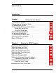
power hard disk (SPEED) light access light I power button diskette drive I I hard disk or diskette drive bay option card slots