
Owner manual
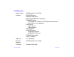

Specifications Page 105
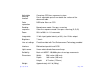
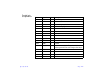
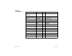
Parallel pin
assignments:
Pin No. Signal I/O Description
1
STROBE
I Data strobe pulse
2-9 DATA 0-7 I/O 8-bit data bus
10
ACKNLG
O Acknowledge symbol
11 BUSY O Scanner busy signal
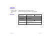
12 NC — Not used
13 GND — Ground
14-15 NC — Not used
16 GND — Ground
17 C_GND — Frame ground
18 NC — Not used
19-30 GND — Ground
31
INIT
I Scanner reset signal. The pulse width at the
receiving terminal must be longer than 50
µ
s.
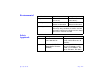
32 NC — Not used
33 GND — Ground
34, 35 NC — Not used
36 DIR I Direction