Advanced Force Measurement Model 9840 Digital Process Monitor Interface, Inc. 7401 E. Butherus Dr.
I N T E R F AC E M O D E L 9 8 4 0 V E R 6 . 0 . 2 CONTENTS CONTENTS .................................................................................................................................................. 1 INTRODUCTION ........................................................................................................................................ 4 QUICK START .................................................................................................................................
I N T E R F AC E M O D E L 9 8 4 0 V E R 6 . 0 . 2 Communications Settings ......................................................................................................................... 25 Communications Format.......................................................................................................................... 25 RS232 RUN MODE COMMAND SUMMARY....................................................................................... 25 RS232 RUN MODE COMMANDS....................
I N T E R F AC E M O D E L 9 8 4 0 V E R 6 . 0 . 2 Option View Command (OV).................................................................................................................... 45 Option Printer Baudrate Command (OP) ................................................................................................ 45 Option Auto-Identify Command (OI)........................................................................................................ 46 Option Auto-Zeroing Command (OZ) .....
I N T E R F AC E M O D E L 9 8 4 0 V E R 6 . 0 . 2 INTRODUCTION The Model 9840 is a CE compliant and versatile precision instrument intended for the digital readout of strain gage sensors such as load cells and torque cells. Optical encoders are also supported. Here is a quick listing of its features: • Full bi-polar 6 digit display (±999,999) using two line, 20 character, vacuum fluorescent display for clear, precise indication of measured quantities and limit status. • No knobs or dials.
I N T E R F AC E M O D E L 9 8 4 0 V E R 6 . 0 . 2 • Remote operation using standard RS232 ASCII command set. • Each unit is set up to interact with the InterView software that can save tests, export data to a spreadsheet, and much more. • Back panel digital inputs for tare, peak and valley reset, position reset, and print. Other functions available as custom programmed options. MODEL 9840 PG 5 PUB.
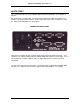
I N T E R F AC E M O D E L 9 8 4 0 V E R 6 . 0 . 2 QUICK START This section will help you get your Model 9840 set up and operating in just a couple of minutes. The back panel is shown below. You will need to make at least two connections here. First be sure that the power switch is off (the lower part of the rocker should be pressed in). Connect the AC power line and plug it in. MODEL 9840 BACK PANEL Next connect a load or torque cell to the 9 pin female connector labeled “Load A”.
I N T E R F AC E M O D E L 9 8 4 0 V E R 6 . 0 . 2 # Message 1 Interface X.Y.Z This is the version number. 2 Serial # 12345 This is the serial number. Option # 114236 This is the option number. 3 4 5 Meaning Last ID A LD90437 The serial number of the load cell on Ch A. Last ID B TQ12030 The serial number of the torque cell on Ch B Ch A Max 4.00Lb Maximum rated load of the sensor on channel A. Ch B Max 4.00LbI Maximum rated torque of the sensor on channel B. Ch A Cal 4.
I N T E R F AC E M O D E L 9 8 4 0 V E R 6 . 0 . 2 The rightmost button will change the units that are being used. Repeated presses of this button will cycle through the list of units available for the currently displayed item. For example, with Load A showing you would see Lb, kg, N, PSI, MPa, Klb, kN, t, mV/V, grams, and then back to Lb. With Torq A, you will see LbI, NM, OzI, and mV/V.
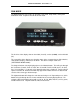
I N T E R F AC E M O D E L 9 8 4 0 V E R 6 . 0 . 2 RUN MODE The Model 9840 has three modes of operation, Run mode, Setup mode, and System Calibration mode. At power-on it will be in Run mode. The first line of the display show an item label (Load A), a value (0.0000), and a unit label (Lb). The second line of the display can show the status of the 4 contact closure limit switches, show another display, show text, or be blank. The above example shows text (“INTERFACE MODEL 9840”).
I N T E R F AC E M O D E L 9 8 4 0 V E R 6 . 0 . 2 The table below summarizes the options. Whether the user sees torque or load for each channel depends upon the cell type that was calibrated or selected for that channel. Load A/B Peak A/B (Load) Valley A/B (Load) Gross A/B (Load) Channel A+B (Ld) Torq A/B Peak A/B (Torque) Valley A/B (Torque) Gross A/B (Torque) Channel A+B (Tq) Position Velocity Limits Pounds, Kilograms, Newtons, PSI, MegaPascals, Kilo-Pounds, Kilo-Newtons, Metric Tons, mV/V, grams.
I N T E R F AC E M O D E L 9 8 4 0 V E R 6 . 0 . 2 The load or torque is always reset to zero. A single channel unit will automatically set Load A or Torque A to zero. Reset Button The Reset button brings up a list of things that you might want to set to zero: If this is a 2-channel unit, the following menu will appear: > Reset Ch A + Ch B will reset the peak and valley for channels A and B. > Reset Ch A Only will reset the peak and valley for channel A.
I N T E R F AC E M O D E L 9 8 4 0 V E R 6 . 0 . 2 Print Button If the Print option is purchased, the Print Button can be used to either print data or to freeze the display. If the Hold option is purchased, the functionality of the button is set using the System Setup options. Otherwise, the button can only control the ability to print data. In Run Mode, if the System Setup Options Print/Hold button is set to Hold, the Print button will freeze and unfreeze the run mode numerical display.
I N T E R F AC E M O D E L 9 8 4 0 V E R 6 . 0 . 2 SETUP MODE SUMMARY The table below summarizes the setup mode menus. Detailed information about each individual item is presented in the following sections. Setup mode ╠══════ ║ ║ ║ ╠══════ ║ ║ ╠══════ ║ ║ ╠══════ ║ ║ ║ ║ ║ ║ ╠══════ ║ ║ ║ ║ ╠══════ ║ ║ ║ ║ ║ ║ ║ ╠══════ ║ ╚══════ MODEL 9840 >User Data Entry ╠════════ ╚════════ >>Base Area Ch A/B >>Base Length >Analog Output ╚════════ Source → Units → Full → Zero.
I N T E R F AC E M O D E L 9 8 4 0 V E R 6 . 0 . 2 SETUP MODE Setup mode is used to change the setup of the Model 9840. To enter setup mode press the two end buttons at the same time ( “<“ and “>“ ). The row of four buttons will now function as indicated by the lower set of labels (Plus, Minus, Enter, and Escape). If the optional keylock is in the locked position you will see “>Setup is Locked” when you try to enter setup mode. This prevents accidental or unauthorized changes to the setup of the unit.
I N T E R F AC E M O D E L 9 8 4 0 V E R 6 . 0 . 2 Entering Numerical Data At times you will need to enter numerical data into the Model 9840. The method is consistent in all cases. A number is presented on the left side of the display with an underline cursor. • • • • • • • Left ( “<“ ) moves the cursor left one position. If you are on the leftmost digit a new zero will be added. Thus 10.000 will become 010.00 where the cursor has moved from the tens place to the hundreds place.
I N T E R F AC E M O D E L 9 8 4 0 V E R 6 . 0 . 2 1. Source: -- This entry allows you to scroll through a list (using the left/right or plus/minus buttons) to select the source of the data that will drive the analog output. The standard list will include load or torque, peak, valley, gross, position, and velocity. Channel A+B is an option which, if chosen, will appear only if the cells on both channels are of the same type. Press enter to select the displayed item. 2.
I N T E R F AC E M O D E L 9 8 4 0 V E R 6 . 0 . 2 2. Full = 4.0000 Lb Zero = 4.0000 Lb (Input) Mv/V (Output)Volt (Output) MA 4 3 2 1 0 -1 -2 -3 -4 0v -2.5v -5.0v -7.5v -10.0v -10.0v -10.0v -10.0v -10.0v 12mA 10mA 8mA 6mA 4mA 4mA 4mA 4mA 4mA 3. Full = 2.0000 Lb Zero = 0.0000 Lb (Input) Mv/V (Output) Volt (Output) MA 4 3 2 1 0 -1 -2 -3 -4 10.0v 10.0v 10.0v 5.00v 0v -5.0v -10.0v -10.0v -10.0v 20mA 20mA 20mA 16mA 12mA 8mA 4mA 4mA 4mA 4. Full = 2.0000 Lb Zero = 2.
I N T E R F AC E M O D E L 9 8 4 0 V E R 6 . 0 . 2 return to the setup mode main menu without changing the cell that is selected. The enter button will select the currently displayed cell and briefly display the rated load or torque, last calibration date, and excitation voltage. To add new cells to this list use the Calibration entry on the setup mode main menu described below.
I N T E R F AC E M O D E L 9 8 4 0 V E R 6 . 0 . 2 >>Cal Check Selecting this item will run a calibration check on the cell attached to Channel A or B. The Model 9840 will measure the shunt value of the cell and compare it to the shunt value that was recorded when the cell was last calibrated. The rated load or torque and last calibration date for the cell are displayed followed by the currently measured shunt value and the shunt value that was recorded when the cell was calibrated.
I N T E R F AC E M O D E L 9 8 4 0 V E R 6 . 0 . 2 set the torque. When the Model 9840 is reading the cell it will display the “Reading...” message for about 10 seconds. During this time it is important that the masses or torque are not disturbed since all the readings taken are averaged together to obtain the calibration data. The second mass/torque is then entered and read. If 5 Point calibration was selected, masses/torque three through five will be entered and read.
I N T E R F AC E M O D E L 9 8 4 0 V E R 6 . 0 . 2 7. Trip if source < / > Set -- Choosing source>set means that the limit will be activated when the source becomes larger than the set point. Choosing source
I N T E R F AC E M O D E L 9 8 4 0 V E R 6 . 0 . 2 >>Com Address This item allows you to set the address of this unit used for the RS232 ASCII command set. Valid values are 1 through 254. If the RS232 multi-drop option is installed you must be sure that all the attached units have different addresses to prevent data collisions. >>Com Baudrate This sets the baud rate for the RS232 ASCII command set. Available values are: 300, 600, 1200, 2400, 4800, 9600, and 19.2k.
I N T E R F AC E M O D E L 9 8 4 0 V E R 6 . 0 . 2 >>Decimals Ch A/B This lets you set the maximum number of digits to the right of the decimal that are displayed or printed for load or torque, peak, and valley. When large cells are selected the number of decimal digits shown may be limited, for example a 100 Lb cell will allow 3 digits, while a 1000 Lb cell will only allow 2 digits. Also if a number is too large to fit on the display some decimal digits may be dropped (the display will “auto-range”).
I N T E R F AC E M O D E L 9 8 4 0 V E R 6 . 0 . 2 REMOTE OPERATION Digital Inputs There are 4 digital inputs available on the Model 9840. They are accessible on the Digital I/O connector on the back panel (pins 9 - 16). These inputs are individually opto-isolated and include current limiting resistors. An input voltage anywhere from +4 to +22 volts DC may be used to obtain the “on” state. See Appendix B for a full description of the Digital I/O connector.
I N T E R F AC E M O D E L 9 8 4 0 V E R 6 . 0 . 2 Communications Settings The Model 9840 supports remote operation using a standard Remote interface consisting of ASCII characters and terminal emulation software package such as HyperTerminal or ProComm. The baud rate is set using the Com Baud rate item on the System Options menu. Supported rates are 300, 600, 1200, 2400, 4800, 9600, and 19.2k baud. There must be 8 data bits, no parity, and 1 stop bit.
I N T E R F AC E M O D E L 9 8 4 0 V E R 6 . 0 . 2 RS232 RUN MODE COMMANDS The commands listed in this section mirror (and in some cases extend) the functions that are available from the front panel of the Model 9840 when it is in Run Mode. Each entry will include the name of the command, followed by a short description that includes the command format, an example that shows what you would type (shown in plain font) and what the Model 9840 would return (shown in italics).
I N T E R F AC E M O D E L 9 8 4 0 V E R 6 . 0 . 2 These are the units for Velocity: 00 – I/M 01 – C/M Front Panel Display Command (F) This command is used to set the front panel display of the Model 9840 to a desired combination of item and unit. There are five subcommands: Front panel View (FV), Front panel Set (FS), Front panel Alternate(FA), Front panel pointer control to line 1 (F1), and Front panel pointer control to line 2 (F2) .
I N T E R F AC E M O D E L 9 8 4 0 V E R 6 . 0 . 2 @123F1 Acknowledge: @123 Active Display shows Load A in Lb Other Display shows Peak A in Lb Front Panel Pointer Control to Line 2 (F2) The Front Panel Pointer Control to Line 2 (F2) assigns the view pointer control to display line 2 (lower line of the display, or the virtual display line if line 2 is disabled) and shows what is on the display. This allows the operator to know which line will be configured or accessed.
I N T E R F AC E M O D E L 9 8 4 0 V E R 6 . 0 . 2 The repeat number is exactly like the one channel command. It must be 0, 1, or 2. Choosing repeat 1 will make the Model 9840 send you the desired value once. Choosing repeat 2 will make the Model 9840 send the value at approximately 3 second intervals. Choosing repeat 0 will turn off any values that are being sent by a repeat 2 command. Example 1: @123V5000002 Acknowledge 2: @123 Load A 120.45 Lb @123 Load A 125.29 Lb ..... @123 Load A 128.
I N T E R F AC E M O D E L 9 8 4 0 V E R 6 . 0 . 2 @123R1000000 Acknowledge: @123 Reset – Tare A Example 2: @123R0111000 Acknowledge 2: @123 Reset – Peak A Valley A Tare B Freeze Display Command (X) In Run Mode, the freeze display command will freeze and unfreeze the run mode numerical display and the values sent from the unit for RS232 output using either the remote Value or Print command. Send the command once to freeze the display and output at the current value.
I N T E R F AC E M O D E L 9 8 4 0 V E R 6 . 0 .
I N T E R F AC E M O D E L 9 8 4 0 V E R 6 . 0 . 2 RS232 SETUP MODE COMMANDS The commands in this section allow you to change the setup of the Model 9840. You will notice that these commands form a menu which approximately duplicates the Setup Mode menu used during setup of the Model 9840 from the front panel. There are additional commands that are for RS232 use only. If the optional Keylock is installed and locked you will not be to alter the setup until the unit has been unlocked.
I N T E R F AC E M O D E L 9 8 4 0 V E R 6 . 0 . 2 Analog Output Command (A) This command is used to view or set the analog output of the Model 9840. There are two subcommands Analog View (AV) and Analog Set (AS). Analog Output View Command (AV) The Analog View (AV) command has the format AV. It will return the current settings of the analog output. Example: @123AV Acknowledge: @123 Analog Output A is Load A in Lb 10.0 Volts indicates 1000 Lb 0.0 Volts indicates 0.
I N T E R F AC E M O D E L 9 8 4 0 V E R 6 . 0 . 2 Example: @123SA Acknowledge: @123 This is the list of cell calibration data: Ch A = S/N 123456, 100.00 Lb , 3.00150 mV/v, 10.00 V , Cal on Oct27-99, 49.532 Lb Shunt Sensor View Command (SV) The Sensor View (SV) command has the format SV.
I N T E R F AC E M O D E L 9 8 4 0 V E R 6 . 0 . 2 Example: @123SD13368# Acknowledge: @123 Deleted Sensor S/N 13368 Ch A = S/N 123456, 100.00 Lb , 3.00150 mV/v, 10.00 V, 49.532 Lb Shunt unused S/N 63220, 100.00 Lb , 2.99984 mV/v, 10.00 V, 49.381 Lb Shunt Ch B = S/N 89991, 1000.0 Lb , 4.50015 mV/v, 5.00 V, 486.45 Lb Shunt Calibration Command (C) This command has 8 subcommands. Calibration Check (CC) is used to run a shunt calibration check on a cell.
I N T E R F AC E M O D E L 9 8 4 0 V E R 6 . 0 . 2 command to stop this calibration. Another method of overwriting existing data is to delete the sensor first and then calibrate. The CB1 Command has been modified to accept the cell type but is still usable by older software.
I N T E R F AC E M O D E L 9 8 4 0 V E R 6 . 0 . 2 Calibration Escape Command (CE) The Calibrate Escape (CE) command is used to cancel a calibration that was started with the Calibrate Begin (CB) command. This format is CE. Example: @123CE Acknowledge: @123 Calibrate Command - Canceled, Calibration NOT Changed Calibrate by Millivolt-Per-Volt Command for One Point (CV) The Calibrate by milli-volt per Volt (CV) command is used to calibrate a load cell using its millivolt per volt calibration constant.
I N T E R F AC E M O D E L 9 8 4 0 V E R 6 . 0 . 2 Calibration by mV/V Mass 1 (CMVM1) command. The mass is entered using the following format: CMVM1(mass value)#. Entering this command will result in the unit prompting the user for the first milli-volt per volt command. Example: @123CMVM15.0005# Acknowledge: @123 Calibrate Mass 1 Command entered Ready for mV/V Value CMVV1 or CE command The CE or Calibration Escape command will, if entered, end this calibration without calibrating the unit.
I N T E R F AC E M O D E L 9 8 4 0 V E R 6 . 0 . 2 Calibration by mV/V Torque 1 (CMVT1) command. The torque is entered using the following format: CMVT1(torque value)#. Entering this command will result in the unit prompting the user for the first milli-volt per volt command. Example: @123CMVT15.0005# Acknowledge: @123 Calibrate Torque 1 Command entered Ready for mV/V Value CMVV1 or CE command The CE or Calibration Escape command will, if entered, end this calibration without calibrating the unit.
I N T E R F AC E M O D E L 9 8 4 0 V E R 6 . 0 . 2 Acknowledge: @123 Calibrate by Mass – 5 Point Ready for CMP1 command Calibrate by Masses Point Command (CMP) The Calibration by Masses Point (CMP) command can have up to six parts: CMP1 through CMP5 and CMP0. You must have already started a calibration using the CB and CM commands for any of these commands to function. To read the first mass issue the Calibration Mass Point 1 (CMP1) command. The format is CMP1(mass)#.
I N T E R F AC E M O D E L 9 8 4 0 V E R 6 . 0 . 2 10.00 V , unused S/N 13368, 10.00 V, unused S/N 63220, 10.00 V , Ch B = S/N 89991, 5.00 V , Cal on Oct27-99, 49.532 Lb Shunt 10.00 Lb , 3.00121 mV/v, Cal on Oct27-99, 4.9292 Lb Shunt 100.00 Lb , 2.99984 mV/v, Cal on Oct27-99, 49.381 Lb Shunt 1000.0 Lb , 4.50015 mV/v, Cal on Oct27-99, 486.45 Lb Shunt Calibrate by Torque Command (CT) The Calibrate by Torque (CT) command tells the unit that you are doing a calibration by 2 point torque or by 5 point torque.
I N T E R F AC E M O D E L 9 8 4 0 V E R 6 . 0 . 2 from the cell before entering this command since it will perform the shunt calibration measurement that is recorded for use with the calibration check command. The format is CTP0. Example: @123CTP0 Acknowledge: @123 Calibrate Command - Reading for Shunt Check... [10 seconds delay] @123 Calibrate Command Completed Ch A = S/N 123456, 100.00 LbI , 3.00150 mV/v, 3.00230 mV/v, 3.00238 mV/v, 3.00353 mV/v, 10.00 V , Cal on Oct27-99, 49.
I N T E R F AC E M O D E L 9 8 4 0 V E R 6 . 0 . 2 The Calibration counts per Inch View (CIV) command displays the current setting of the encoder counts per inch constant. Example: @123CIV Acknowledge: @123 Encoder is 32000 counts per inch The Calibration counts per Inch Set (CIS) command allows you to change the current setting of the encoder counts per inch constant.
I N T E R F AC E M O D E L 9 8 4 0 V E R 6 . 0 . 2 The limit number chooses which limit (1-4) you want to setup. The normal position should be set to 0 for normally open or 1 for normally closed. The enable should be set to 0 for disabled or 1 for enabled. If the limit is disabled the rest of this command may be omitted (see example 3). The item and unit numbers indicate which signal is to drive this limit. The set point number indicates the signal level at which the limit is to be activated.
I N T E R F AC E M O D E L 9 8 4 0 V E R 6 . 0 . 2 @123LE Acknowledge: @123 Limit Setup Command Canceled Limit Reset Command (LiR) The Limit Reset (LiR) command is used to manually reset a latching limit that has been activated. The format is L(limit number)R. Example: @123L1R Acknowledge: @123 Reset Limit 1 System Options Command (O) The system Options command has 8 subcommands that are used to view or set the options that appear on the system options menu.
I N T E R F AC E M O D E L 9 8 4 0 V E R 6 . 0 . 2 Example: @123OP9 Acknowledge: @123 Printer Baud Rate is 230.4K Option Auto-Identify Command (OI) The Option auto-Identify (OI) command is used to turn auto-identification of load cells on or off. The format is OI(0 or 1), where 0 turns auto-id off, and 1 turns autoid on. Option Printer Command Code Baudrate 4 4800 5 9600 6 19.2K 8 57.6K 9 230.
I N T E R F AC E M O D E L 9 8 4 0 V E R 6 . 0 . 2 Option Com Baudrate Command (OB) The Option com Baudrate (OB) command is used to change the communications baudrate for this unit. The format is OB(code), where the baudrate codes are given in the table. Code 7 is a special baudrate that is reserved for future expansion. Note that the acknowledgement is given at the current baudrate and then the baudrate is changed.
I N T E R F AC E M O D E L 9 8 4 0 V E R 6 . 0 . 2 @123 RS232 EOT is on. Display Options Command (D) The Display options command has 5 subcommands used to set options that effect the front panel display of the Model 9840. Display View Command (DV) The Display View (DV) command is used to return the current values of all the display options. The format is DV.
I N T E R F AC E M O D E L 9 8 4 0 V E R 6 . 0 . 2 Display Count By Command (DC) The Display Count by (DC) command sets the smallest number that the display will count by for the Load or Torq, Peak, and Valley measurements. The format is DC(channel)(code) where the code is selected from the table at the right.
I N T E R F AC E M O D E L 9 8 4 0 V E R 6 . 0 . 2 Disabling the window sets this value to 0. The window, once enabled and set, will take effect immediately and will remain in effect until the window is disabled. Note that changing a cell type on a channel will automatically disable the filter window for that channel, reset the units to Lb or LbI, and set the window value to 0. The window must then be reset and re-enabled by the user.
I N T E R F AC E M O D E L 9 8 4 0 V E R 6 . 0 . 2 SYSTEM CALIBRATION MODE The following procedure should be followed to calibrate the Model 9840 itself. This calibration requires the use of a precision millivolt per volt reference which will be attached on the load cell connector. The resulting scale factors are recorded in the non-volatile memory of the Model 9840.
I N T E R F AC E M O D E L 9 8 4 0 V E R 6 . 0 . 2 APPENDIX A -- MODEL 9840 SPECIFICATIONS Transducer Interface Excitation 5VDC or 10 VDC software/auto selectable Current Drive 180 mA at 5VDC or 10 VDC Push Button Shunt Yes Internal Shunt Resistor 1 standard, 2 optional. Rear panel selectable Calibration Method Shunt, mV/V, Known Load Push Button Tare 100% of range--display and analog output Sensitivity Adjust 1mV/V to 4.5 mV/V Accuracy 0.
I N T E R F AC E M O D E L 9 8 4 0 V E R 6 . 0 .
I N T E R F AC E M O D E L 9 8 4 0 V E R 6 . 0 . 2 Digital Display Display Characters 2 lines by 20 characters Display Update > 4/Sec Scaling Automatic or manual Maximum Display Count ± 999,999 Decimal Points. Selection 0 to 5 software selectable.
I N T E R F AC E M O D E L 9 8 4 0 V E R 6 . 0 . 2 APPENDIX B -- CABLES AND CONNECTORS Load Cell Connectors Pin 1 2 3 4 5 6 7 8 9 DB9 Female Signal EXCITE - HI SENSE - HI1 CELL OUTPUT - HI CELL OUTPUT - LO SENSE - LO 1 EXCITE - LO AUTO ID - A AUTO ID - B CHASSIS GND Notes: 1. If the sense lines are not used, SENSE - HI must be tied to EXCITE - HI and SENSE - LO must be tied to EXCITE - LO. 2. Incorrect wiring of these ports can cause damage to the internal circuitry of the unit.
I N T E R F AC E M O D E L 9 8 4 0 V E R 6 . 0 . 2 Digital I/O Connector Notes: High Density 26 Female Pin Signal 1 LIM 1 A1 2 LIM 1 B1 3 LIM 2 A 4 LIM 2 B 5 LIM 3 A 6 LIM 3 B 7 LIM 4 A 8 LIM 4 B 9 ISO IN 1 - HI2 10 ISO IN 1 - LO2 11 ISO IN 2 - HI 12 ISO IN 2 - LO 13 ISO IN 3 - HI 14 ISO IN 3 - LO 15 ISO IN 4 - HI 16 ISO IN 4 - LO 17 KEYLOCK3 18 GND 19 ENCODER CHA-L4 20 ENCODER CHA 21 GND 22 ENCODER CHB-L 23 ENCODER CHB 24 GND 25 GND 26 +12 VDC (+5 VDC optional4) 1.
I N T E R F AC E M O D E L 9 8 4 0 V E R 6 . 0 . 2 USB Connector Pin Name Description 1 VCC +5 VDC 2 D- Data – 3 D+ Data + 4 GND Ground MODEL 9840 PG 57 PUB.
I N T E R F AC E M O D E L 9 8 4 0 V E R 6 . 0 . 2 Precision Shunt Calibration Resistors This diagram shows the connection of the precision internal shunt resistors. The back panel switch (shown to the left of the two resistors) selects between 30 KΩ and 60 KΩ. The shunt check relay (shown to the right of the two resistors) connects the selected resistor between the Excite High and the Cell Output High.