EPSON ® User’s Guide Update In order to take advantage of the latest technology, the system board in your computer has been completely redesigned. This update includes last-minute information that was not available at the time your on-screen User’s Guide was created. External Cache Your computer supports up to 1MB of external cache. If your system already has cache installed, it can be increased up to 1MB. However, you cannot install cache chips yourself.
The illustration below shows the correct location of jumpers and other components on the system board in your computer.
Jumper Settings The jumpers on the system board have been renumbered, as shown in the tables below. The factory default settings are indicated by an asterisk (*).
CPU type jumpers settings CPU clock speed 25 Mhz 33 MHz JP17 I 1-2 I 1-2,3-4,5-6 40 MHz 1-2,3-4 50 Mhz 5-6 EPSON is a registered trademark of Seiko Epson Corporation. Copyright 0 1995 by Epson America, Inc.
EPSON ® User’s Guide a EPA POLLUTION PREVENTER Printed on recycled paper with at least 10% post consumer content @
IMPORTANT NOTICE DISCLAIMER OF WARRANTY Epson America makes no representations or warranties, either express or implied, by or with respect to anything in this manual, and shall not be liable for any implied warranties ofmerchantability and fitness for a particular purpose or for any indirect, special, or consequential damages. Some states do not allow the exclusion of incidental or consequential damages, so this exclusion may not apply to you. COPYRIGHT NOTICE All rights reserved.
Important Safety Instructions Read all of these instructions and save them for later reference. Follow all warnings and instructions marked on the computer. . Unplug the computer before cleaning. Clean with a damp cloth only. Do not spill liquid on the computer. . Do not place the computer on an unstable surface or near a radiator or heat register. . Do not block or cover the openings in the computer’s cabinet. Do not insert objects through the slots. .
Importantes instructions de sbcuritb Lire attentivement les instructions suivantes et les conserver pour les consulter en cas de besoin. Observer soigneusement tous les avertissements et directives marques sur l’ordinateur. l l l Debrancher l’ordinateur avant de le nettoyer. N’utiliser qu’un chiffon humide. Veiller a ne pas renverser de liquides sur l’appareil. Ne pas placer l’ordinateur sur une surface instable ni pres dune source de chaleur.
Wichtige Sicherheitshinweise Bitte lesen Sie diese Sicherheitshinweise, und heben Sie sie zur spateren Verwendung auf. Beachten Sie alle Warnungen und Anweisungen, die auf dem Computer angebracht sind. Ziehen Sie das Netzkabel des Computers vor der Reinigung heraus. Verwenden Sie zur Reinigung nur ein feuchtes Tuch. Achten Sie darauf, dab keine Fltissigkeiten auf dem Computer verschtittet werden.
l Ziehen Sie den Computer heraus, und rufen Sie qualifiziertes Wartungspersonal, wenn eine der folgenden Bedingungen auftritt: Das Netzkabel oder der Netzstecker ist beschadigt; Fltissigkeit ist in den Computer eingetreten; der Computer wurde fallengelassen oder das Gehause ist beschadigt; der Computer funktioniert nicht ordnungsgemain oder die Leistung hat sich merklich geandert. Stellen Sie nur die Bedienelemente ein, die in der Gebrauchsanweisung beschrieben sind.
Your new EPSON@ computer is a full powered, full featured system that gives you complete access for all your business or home computer needs. And because your computer is plug and play compliant and designed to take advantage of Microsoft@ Windows® 95, you’ll be able to use all the latest technology. With the computer’s high-performance processor and memory you can run a vast array of the latest programs, utilities, and games designed for productivity and fun.
High-speed, PC1 video controller with 64-bit DRAM video interface and 32-bit CPU interface Two PCI ATA-2 compatible, enhanced IDE interfaces supporting up to four IDE devices, such as hard disk drives and CD-ROM drives (two on each interface) 8 or 16KB of internal cache in the processor and up to 512KB of external cache on the main system board 1MB of on board video memory for resolutions up to 1024 x 768; memory expandable to 2MB Three Energy Star compliant power-saving modes for the CPU, video, and hard d
ISA and PCI Expansion Buses Your computer includes expansion buses for two types of option cards: ISA and PCI. The PCI bus provides extremely fast data transfer (33 MHz) for up to two high-performance PCI cards, such as high-speed video cards. PCI cards use plug and play technology that automatically configures resources used by the card, such as interrupt requests and memory addresses. The ISA bus transfers data at 8.33 MHz for up to three 16-bit ISA option cards.
Chapter 1 provides instructions for setting up your system and connecting peripheral devices such as the monitor and printer. Chapter 2 describes how to run the SETUP program to change your computer’s configuration and how to install the PCI IDE and video drivers. Chapter 3 covers general operating procedures, such as using your Green PC features and using a password.
0 Customer relations 0 EPSON technical information library fax service 0 Product literature on current and new products. You can purchase printed manuals, accessories, or parts for EPSON products from EPSON Accessories at (800) 873-7766 (U.S. sales only). In Canada, call (800) BUY-EPSON. If you purchased your computer outside the United States or Canada, contact your EPSON dealer or the marketing location nearest you for customer support and service.
CompuServe online support CompuServe® members can call the Epson America Forum on CompuServe. If you are already a member, simply type GO EPSON at the menu prompt to reach the Forum. If you are not currently a member, you are eligible for a free introductory membership as an owner of an EPSON product. This membership entitles you to: 0 An introductory credit on CompuServe 0 Your own user ID and password 0 A complimentary subscription to CompuServe Magazine, CompuServe’s monthly publication.
Contents Introduction Computer Features . . . . . . . . . . . . . . . . . . . . . . . . . Power-saving Features . . . . . . . . . . . . . . . . . . . . . . . ISA and PCI Expansion Buses . . . . . . . . . . . . . . . . . . . System and Video BIOS . . . . . . . . . . . . . . . . . . . . . . How to Use This Manual . . . . . . . . . . . . . . . . . . . . . . Where to Get Help . . . . . . . . . . . . . . . . . . . . . . . . . Electronic Support Services . . . . . . . . . . . . . . . . . .
Chapter 3 Using Your Computer Working Comfortably . . . . . . . . . . . . . . . . . . . . . . . . . . . 3-1 Using the Right Furniture . . . . . . . . . . . 3-2 Positioning Your Monitor . . . . . . . . . . . 3-3 Lighting Your Workspace . . . . . . . . . . . 3-4 Using the Keyboard and Mouse . . . . . . . . 3-4 Maintaining Good Posture and Work Habits . . . . . . . . . . . 3-5 Backing Up Your Files . . . . . . . . . . . . . . . . 3-6 Using Energy Wisely . . . . . . . . . . . . . . . . .
Chapter 5 Ins falling and Removing Slim line Drives Removing the Drive Mounting Bracket . . . . . . . . . . . . . Installing a Hard Disk Drive in the Mounting Bracket . . . . . Setting the IDE Device Jumpers . . . . . . . . . . . . . . . Installing the Hard Disk Drive . . . . . . . . . . . . . . . Replacing the Bracket in the Computer . . . . . . . . . . . Connecting the Drive Cables . . . . . . . . . . . . . . . . . Reconnecting the Cables to the Diskette Drive . . . . . . .
CD-ROM Drive Problems . Password Problems. Software Problems. Printer or Scanner Problems . Option Card Problems . Memory Module Problems . Controller Problems. . External Cache Problems . . . . . . . . . . . . . . . . . . . . . . . . . . . . . . . . . . . . . . . . . . . . . . . . . . . . . . . . . . . . . . . . . . . . . . . . . . . . . . . . . . . . . . . . . . . . . . . . 7-12 7-12 7-13 7-14 7-15 7-16 7-17 7-17 Appendix A Specifications CPU and Memory . . . . . . . . . . . . .
Chapter- 1 Setting Up Your System This chapter briefly describes how to set up your computer if you didn’t set it up already using the information in your User's Digest. It includes the following information: 0 Choosing a location 0 Setting the voltage selector switch 0 Connecting system components 0 Turning the computer on and off. Choosing a Location Before you set up your system, choose a convenient location that provides a flat, hard surface.
Setting the Voltage Selector Switch Your system is powered by a 200 Watt power supply. The power supply input voltage is controlled by a switch on the computer’s back panel that may be set to 110 VAC or 220 VAC. (The switch on your computer may read 115 VAC or 230 VAC; these are equivalent settings.) The computer is shipped with the voltage selector switch set to 110 VAC, which is appropriate for line source voltages between 100 and 120 VAC.
Connecting System Components Use the illustrations below to locate the ports on the back of your system as you connect the keyboard, monitor, printer, and other devices. The icons on the case identify the function of each port. slimline computer keyboard mouse serial 1 serial 2 \ .
Connecting a Keyboard or Mouse Refer to the illustrations under “Connecting System Components” as you connect your keyboard and mouse. :‘==.::‘I To connect the keyboard, hold the cable connector so the arrow on the connector faces the icon on the computer case. Insert it into the keyboard port, marked with the icon shown at the left. To connect the mouse, insert the connector into the computer’s built-in mouse port so the arrow or mark on the connector faces the icon on the computer case.
There should be two cables provided with your monitor: the monitor cable (to connect it to the computer) and the power cable (to connect it to a power source). On most monitors, the monitor cable is permanently attached to the monitor. If your monitor does not have an attached cable, connect the cable to it now. Examine the connector on the monitor cable and line it up with the monitor port on the computer. Then insert the connector into the port. Iu This icon identifies the SVGA monitor port.
Connecting a Parallel or Serial Device Your computer has one multi-mode parallel (printer) port and two serial ports. To connect a printer or other peripheral device, refer to the illustrations under “Connecting System Components” as you follow the appropriate instructions in this section. Using the parallel (printer) port Follow these steps to connect a parallel device to your computer: 1. Place the parallel device and the computer so that the backs are facing you. 2.
Note If you use ECP mode (Extended Capabilities Port), check your parallel device software documentation for the correct DMA channel (DRQ) setting. Then set jumpers JP8 and JP18 to match this setting if necessary. See “Changing the Jumper Settings” in Chapter 4 for more information. Using the serial ports If you have a printer, a modem, or other device with a serial interface, you can connect it to one of the serial (RS-232C) ports. Make sure you have a cable compatible with a DB-9P connector.
WARNING To avoid an electric shock, be sure to plug the cord into the computer before plugging it into the wall outlet. 2. Plug the other end of the cord into an electrical outlet. Turning On the Computer Once you set up your system, you’re ready to turn on the power. Refer to the illustrations below to locate the POWER button and other features on the front panel.
POWER light Tower computer SPEED light hard disk light access POWER button RESET button drive bays Before you turn on your system, be sure to read “Important Follow these steps to turn on your system: 1. Turn on the monitor, printer, and any other devices connected to the computer. 2. Turn on the computer by pressing the POWER button on the front panel.
You may want to run SETUP to adjust power saving features or establish passwords. See Chapter 2 for instructions. If you don’t press Del, your computer loads the operating system. Turning Off the Computer Whenever you turn off your system, follow these steps: 1-10 1. Save your data, exit any application programs, and exit or shut down Windows. If you see a message, wait until it says you can safely turn off your computer. 2. Check the drive lights to make sure they are not on.
Chapter 2 Running SETUP and Installing Drivers If you’ve added options or you want to customize your computer, you can use a configuration program called SETUP, which is contained within the BIOS on the system board. SETUP allows you to change the settings for your hardware configuration, security options, and power-saving features.
Starting the SETUP Program When you start your computer, it performs some power-on diagnostics. During these diagnostics, you may see the following message: Press to enter SETUP Press Del. This message is only on the screen for a few seconds. If you missed it, restart your computer and try again.
The table below lists some of the keys you can use to perform SETUP operations.
System Setup options Option Settings Description System Time System Date hh:mm:ss mm dd, yyyy Sets the time and date: once they are set, you should not need to change them, unless you adjust the time for daylight savings or a different time zone (the computer automatically changes the date for leap years) Video System EGA/VGA * Monochrome CGA 80X25 Defines the type of display you are using: if you have connected a VGA or SVGA monitor to the built-in monitor port, select EGA/VGA (1) System Memory E
Using the Fixed Disk Setup Option The Fixed Disk Setup option defines the types of hard disk drives connected to the primary and secondary IDE interfaces in your system. When you select this option, you see the Fixed Disk Setup screen. Note These options do not configure other IDE devices, such as CD-ROM drives, connected to the secondary IDE interface.
Some older drives may not support the auto-sensing feature. If the drive parameters sensed by the computer do not match your drive, define your own drive type or reformat the disk. You may also need to set the remaining options on the screen. See the next section for instructions on defining your own drive type. The Multi-Sector Transfers option sets the number of sectors per block that the hard disk uses in multiple sector transfers. The auto-sensing feature sets this option appropriately for your drive.
Using the Advanced System Setup Options When you select the Advanced System Setup option, you see the Advanced System Setup screen, from which you can configure the computer’s integrated peripheral devices (such as the parallel and serial ports), cache memory, shadow memory, the advanced chip set features, and PCI devices. To avoid possible configuration problems, it is a good idea to leave these options at their default settings.
The Integrated Peripherals options are described in the table below.
Configuring cache memory Enabling cache memory improves system performance when retrieving and processing large amounts of data on systems with external cache installed. To avoid possible configuration problems, leave these options at their default settings unless a peripheral you have installed requires that you make changes. See your peripheral documentation for information. The table below lists the memory cache options.
Configuring shadow memory You can enable video BIOS shadowing or configure shadowing for specific option ROM memory blocks. Note For the best system performance, always leave the System shadow and Video shadow options set to Enabled (the default setting). Your computer can access RAM faster than ROM. The options on this screen allow your system to copy the contents of its video ROM and any optional ROMs into RAM.
The table below lists the advanced chipset options.
Setting the Boot Options When you select Boot Options from the Main Menu, you see the Boot Options screen, which allows you to define the drive boot sequence and determine which power-on diagnostic tests the computer performs when you start your system. The Boot sequence option determines the order in which the computer checks the drives for an operating system when you turn it on or reset it. The table below describes the available options.
Selecting the Security and Anti-Virus Options When you select Security and Anti-virus from the Main Menu, you see the Security and Anti-Virus screen, which allows you to set passwords and other options, as described below. Selecting password types You can define both User and Supervisor password levels for this system.
Entering or changing passwords To specify a User password, you must first specify a Supervisor password. Follow these steps to enter or change a password: 1. Select Set Supervisor Password and press Enter. 2. You see a Set Supervisor Password window. Type a password of up to seven characters and press Enter. 3. Type the same password a second time and press Enter. You see a message that your changes have been saved. 4. Press the spacebar. The Supervisor Password option now displays Enabled.
Using the virus protection features The Diskette access option allows you to restrict access to your diskette drives based on the password levels you have defined. This prevents unauthorized users from accessing the drives and possibly introducing a virus to your system. You can restrict diskette access only if passwords are enabled and you have enabled the Password on boot option.
Using the Green PC Features Select Green PC Features from the Main Menu to view the Green PC Features screen. The options on this screen allow you to control the computer’s Energy Star compliant, power-saving features described in the table below. For more information about the energy-saving operations of your computer, see “Using Your Green PC Features” in Chapter 3.
Green PC options (continued) Option Settings Description System Suspend Timer 2 minutes* 4 minutes 8 minutes 16 minutes 32 minutes 64 minutes 128 minutes 256 minutes 512 minutes Disabled Sets the time period of system inactivity (following any Doze and Standby periods that are set) after which the system enters Suspend mode or allows you to disable entry into Suspend mode VGA with Power Down feature VESA DPMS Standard None * Selects the method the VGA chip uses to enter Doze mode Non_SMI CPU suppor
Exiting SETUP When you leave SETUP, you can save your settings or exit SETUP without saving your settings. You can also return all values to the factory defaults. To leave SETUP, press ESC from any SETUP screen. From the SETUP Main Menu, you can perform the functions described in the table below. Exiting SETUP options Option Description Load ROM Default Values Loads the factory default settings stored in ROM back into CMOS.
In order to install the drivers, you need to create install diskettes using the utility program on your computer. See the User's Digest for instructions. Once you create the diskettes, you can install drivers for these programs: 0 MS-DOS 0 Windows 0 Windows NT 0 OS/ 2® versions 2.0 and higher (2.X) 0 SCO®UNIX versions 3.2.4 and higher (3.2.4.X) 0 Novell®NetWare versions 3.1 and higher (3.1X) 0 Novell NetWare versions 4.0 and higher (4.0X).
Running the Installation Program Follow these steps to install the PCI IDE drivers: 1. Insert the PCI IDE Drivers diskette in drive A. 2. Access the DOS prompt, if you are not there already 3 . T y p e A : and press Enter to log onto drive A. 4. Type 5. INSTALL and press Enter. Follow the instructions on the screen to install the PCI IDE drivers on your hard disk. Note Not all hard disk drives can take full advantage of the PCI IDE interface.
Installing Video Drivers Your system already includes Windows video drivers that let you take full advantage of the performance your computer’s built-in SVGA controller can offer. If you want to install video drivers for DOS applications, you can create install diskettes using the utility program on your computer. See the User's Digest for instructions on using the diskette creation utility. Once you create the video drivers diskettes, follow the instructions in the README file on the diskettes.
Chapter- 3 Using Your Computer This chapter describes the following operations: 0 Working comfortably 0 Backing up your files 0 Using energy wisely 0 Using your Green PC features 0 Inserting and removing diskettes 0 Stopping a command or program 0 Resetting the computer 0 Using a password. Working Comfortably If you spend a lot of time at your computer, you may experience occasional fatigue or discomfort caused by repetitive motions or too much time spent in one position.
Take a few minutes to read this section for suggestions about: 0 Using the right furniture 0 Positioning your monitor 0 Lighting your workspace 0 Using a keyboard and mouse 0 Maintaining good posture and work habits. Using the Right Furniture Selecting a good desk and using the right type of chair can make a big difference in your level of comfort.
Adjust the height of your chair so when you are using the keyboard or mouse your upper arms are vertical and your forearms and wrists are horizontal. For good circulation, your feet should rest flat on the floor with your lower legs vertical and your knees level with your hips. You may need to use a footrest to maintain the correct alignment for your legs.
Lighting Your Workspace Appropriate lighting increases your comfort and productivity, and it’s good for your eyes. Arrange your computer and light sources to minimize glare and bright reflections. Position the monitor so that any windows in the room face the sides of the monitor, not the front or back. This will help reduce glare. For working at the computer, indirect or shielded lighting is best, and it should light your entire office equally.
Keep your hands and fingers relaxed when you are typing and try not to press the keys too hard; using too much force creates tension in your hands. Remove your hands from the keyboard when you are not using it and take frequent breaks to stretch your hands and fingers. When go of Leave move using a mouse, keep your wrist and fingers relaxed. Let the mouse frequently and stretch or relax your hand. enough space on your work surface so you can freely the mouse.
Backing Up Your Files To protect your data, it is a good idea to back up your files regularly. You should also make backup copies of any diskettes you have that contain programs (your system may have come with a utility installed on the hard disk drive to do this for you) and store the copies away from your originals. You can use any backup program or the backup utility in your operating system. Read the online help or the software documentation for instructions.
Using Your Green PC Features Your computer includes features that lower the power usage of the microprocessor and other components when the system has been inactive for a selected period of time. Using the SETUP program, you can customize inactivity timers for three power-saving modes: Doze, Standby, and Suspend. Each of the three modes provides progressively increased levels of power conservation. You can also customize an individual Standby timer for the hard disk drive.
To resume activity when your system is in a power-saving mode, press a key or move the mouse. If your system was in Doze mode, the monitor immediately displays and you can access your system right away. If your system was in Suspend mode, it takes a few moments for the monitor to display and for the hard disk drive to return to active mode. You'll hear it start again.
Tower computer button When you want to remove the diskette, make sure the drive light is off; then press the release button. Remove the diskette and store it properly. caution Never remove a diskette, reset the computer, or turn it off while a diskette drive light is on. You could lose data. Also, remove all diskettes before you turn off the computer. Stopping a Command or Program You may sometimes need to stop a command or program while it is running.
If you are using Windows, press Ctrl Alt Del and follow the instructions on the screen. If these methods do not work, you may need to reset the computer. Do not turn off the computer to exit a program or stop a command unless you have to, because the computer clears any data you did not save. Resetting the Computer Occasionally, you may want to clear the computer’s memory without turning it off. You can do this by resetting the computer.
If resetting the computer does not correct the problem, you probably need to turn it off and on again. Remove any diskette(s) from the diskette drive(s). Turn off the computer and wait 20 seconds. Then turn on the computer. Using a Password Using SETUP, you can define both a Supervisor level password and a User level password. You can also specify whether a password is required when you start the system. This password can control who has access to the diskette drives.
If you don’t enter the correct password the first time you type it, you can try two more times. If you haven’t entered the correct password on the third try, the computer locks up to prevent unauthorized access. You see the message: SYSTEM DISABLED You must either turn off the computer or press the RESET button to start over. In this situation, you cannot reset the computer by pressing Ctrl Alt Del.
Chapter- 4 Installing and Removing Options You can enhance the performance of your computer by adding optional equipment such as option cards, and system, video, or cache memory modules, or by upgrading the processor. If you have this manual online only, be sure to print out the chapter before performing any of the procedures it describes.
Caution Never install options or change jumper settings when the computer is turned on or the power cable is connected. Removing the Cover You need to remove the computer’s cover to install any of the options described or to install or remove a drive (as described in Chapters 5 and 6). Follow these steps: 4-2 1. Turn off the computer and then any peripheral devices. 2. Disconnect the computer’s power cable from the electrical outlet and from the back panel.
5. Remove the screws securing the cover (three on the slim line computer and six on the tower computer), as shown below. Save the screws to secure the cover again when you are through.
6. Grasp the sides of the cover and lift it off as shown below. For the slimline computer, lift up the cover at an angle and then pull it off. For the tower computer, pull the cover straight back until it clears the case.
7. Set the cover aside 8. Ground yourself to the computer by touching the metal surface of the back panel. WARNING Be sure to ground yourself by touching the back panel of the computer every time you remove the cover. If you are not properly grounded, you could generate an electric shock that could damage a component when you touch it. Replacing the Cover When you are ready to replace the computer’s cover, refer to the illustrations above and follow these steps: 1.
Locating the Internal Components As you follow the instructions in this chapter, refer to the illustration below to locate the major components inside your computer.
Tower computer video memory sockets option card connector board hard disk drive mounting bracket i / power T-, supply processor cache y memory sockets tag SRAM - I voltage regulator \ drive bays \ SIMM sockets Installing and Removing Options 4-7
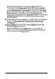
Locating System Board Components The illustration below shows the system board inside your computer. Use this illustration to locate jumpers and drive connectors.
Changing the Jumper Settings The jumpers on the system board are preset to factory default positions, indicated by an asterisk (*) in the tables below. (See the illustration under “Locating the System Board Components” to locate jumpers.) Use the information in this section to change jumper settings, if necessary. Note Any jumpers not listed in the following tables are for service purposes only. Do not change their settings.
CPU type jumper settings CPU type Intel or AMD Intel Jumper 4-10 Installing and Removing Options Cyrix UMC
CPU voltage jumper settings CPU voltage JP1 (on voltage regulator) * 3.3V 1-2 1 3.
Setting the Jumpers To change a jumper setting, follow these steps: 1. Refer to the illustration under “Locating System Board Components” to locate the jumpers. 2. If any option cards are installed in your computer, you may need to remove them to access the jumpers. See “Removing an Option Card” for instructions. 3. A jumper’s setting is determined by where the jumper is placed on the pins. Use the table below to identify the pin settings for 2-, 3-, and 4-pin jumpers.
To move a jumper from one position to another, use needle-nose pliers or tweezers to pull it off its pins and gently move it to the desired position. Caution Be careful not to bend the jumper pins or damage any components on the main system board. 4. Replace any option cards you removed, if necessary. See “Installing an Option Card “for instructions. 5. Replace the computer’s cover as described under “Replacing the Cover.
The following table shows the recommended SIMM SIMM configurations 4-14 Installing and Removing Options
SIMM configurations (continued) and Removing Options 4-15
SIMM configurations (continued) * 32MB Double 32MB Double 32MB Double 32MB Double 32MB Double 32MB Double 32MB 96MB Double 128MB If you install SlMMs in both Bank 0 and Bank 1 or Bank 2 and Bank 3, SIMM types must match. Use only tin-plated, 32-bit, 72-pin, fast-page mode SIMMs that operate at an access speed of 70ns or faster. Be sure all the SIMMs operate at the same speed. Your SIMM illustrations.
Inserting SlMMs Make sure the computer is turned off and the cover is off. Then follow these steps to install SIMMs: 1. Refer to the illustration under “Locating the Internal Components” to locate the SIMM sockets in the corner of the main system board. 2. Remove any option cards that may be blocking your access to the SIMM sockets. (See “Removing an Option Card” for instructions.) 3. Position the SIMM at an angle over the empty socket, with the SIMM components facing the front of the computer.
4-18 4. Push the SIMM into the socket until it is seated firmly in the slot. Then tilt it upright, as shown below, guiding the hole at each end of the SIMM over the retaining post at each end of the SIMM socket. If it does not go in smoothly, do not force it; pull it all the way out and try again. 5. Replace any option cards you removed. (See “Installing an Option Card” for instructions.) 6. Replace the computer’s cover as described under “Replacing the Cover.
Removing SlMMs If you need to remove SIMMs from your computer (to install different ones, for example), follow the steps below: 1. Use the illustration under “Locating the Internal Components” to locate the SIMM sockets in the corner of the main system board. 2. Remove any option cards that may be blocking your access to the SIMM sockets. (See “Removing an Option Card” for instructions.) 3.
5. If you are inserting different SIMMs, follow the instructions under “Inserting SIMMs” to install them. 6. Replace any option cards you removed, as described under “Installing an Option Card.” 7. Replace the computer’s cover as described under “Replacing the Cover. “Then see “Post-installation Procedures” for instructions on configuring your computer with your new memory size. Installing an Option Card This section explains how to install option cards in your computer.
As you install option cards, keep these guidelines in mind: Make sure you know whether the card you are installing is an ISA card or a PCI card, so you can install it in the correct type of slot. If you have an S-bit ISA card, you can install it in a 16-bit ISA slot, as long as it fits. Check the components on your card and the system board before deciding which slot to use. Make sure that no components are touching or obstructing other cards or cables.
Installing a Card in the Slimline Computer /3-slot Side) The option card connector board in the slimline computer has two slots on one side and three slots on the other side. Although the illustration shows an ISA card, you can use the same instructions for installing a PCI card. Follow these steps to install an option card on the three-slot side: 4-22 1. Remove the retaining screw securing the option slot cover to the computer, as shown below. (Keep the screw to secure the option card to the computer.
Once the connectors reach the slot, push the card in firmly (but carefully) to insert it fully. You should feel the card fit into place. If it does not go in smoothly, do not force it; pull the card all the way out and try again. 4. Secure the end of the card to the computer with the retaining screw. Installing a Card in the Slimline Computer (2-slot Side) The option card connector board in the slimline computer has two slots on one side and three slots on the other side.
4-24 3. Hold the card along the top corners and guide it into the slot Once the connectors reach the slot, push the card in firmly (but carefully). You should feel the card fit into place. If it does not go in smoothly, do not force it; pull the card all the way out and try again. 4. Replace the slot cover bracket by inserting it into the small metal holder below the option slots; then replace its retaining screw. 5. Replace the computer’s cover as described under “Replacing the Cover.
Installing a Card in the Tower Computer Follow these steps to install an option card in the tower computer. Although the illustration shows a PCI card, you can use the same instructions for installing an ISA card. 1. Remove the retaining screw securing the option slot cover to the computer, as shown below. (Keep the screw to secure the option card to the computer.) 2. Slide out the slot cover for the slot you are going to use and set it aside.
3. Hold the card along the top corners and guide it into the slot (If you are installing a full-length card, insert the front edge of the card into the corresponding guide inside the computer’s front panel.) Once the connectors reach the slot, push the card in firmly but carefully. You should feel the card fit into place. If it does not go in smoothly, do not force it; pull the card all the way out and try again. 4-26 4. Secure the end of the card to the computer with the retaining screw. 5.
Removing an Option Card You may need to remove an option card to access components on the main system board or if you no longer need it. Refer to the illustrations under “Installing an Option Card” for your computer type as you follow these steps: 1. If you are removing a card from the tower computer or from the three-slot side on the slimline computer, first remove the retaining screw securing the option card to the computer. Then pull the card straight out of the slot. 2.
Note that your video memory sockets may not look exactly like the ones in the illustration. If you’re not sure how to install video memory chips, contact the EPSON Connection or your Authorized EPSON Servicer and ask for assistance. Follow these steps to install video memory chips: 1. Locate the video memory chip sockets on the left side of the main system board, shown under “Locating the Internal Components.” 2. If there is an option card in your way, remove it.
4. Gently press the chip into the socket; then push down firmly on both ends to make sure it is well-seated. 5. Repeat steps 3 and 4 to install the other chip 6. Replace any option cards you removed; see “Installing an Option Card” for instructions. 7. Replace the computer’s cover as described under “Replacing the Cover. “Then see “Post-installation Procedures” for instructions on configuring your computer with the increased video memory.
Cache memory configurations BANK 0 U23,24,25,26 BANK 1 U27,35,36,37 Tag S RAM U30 32K x 8, 28-pin None 32K x 8, 28-pin I 128KB I 32K x 8, 28-pin 32K x 8, 28-pin 32K x 8, 28-pin I 256KB I 64K x 8, 28-pin 64K x 8, 28-pin 32K x 8, 28-pin 128K x 8,32-pin None 32K x 8, 28-pin I 512KB I I 512KB I Note that your cache memory sockets may not look exactly like the ones in the illustration.
3. Inspect each cache memory chip; the pins should point inward at slightly less than a 90° angle. If any of the pins are bent or crooked straighten them gently with your fingers or with small tweezers to align them with the other pins. Be careful when you do this; the pins are fragile and can break off easily. 4. Position one of the cache chips over the first socket as shown below, aligning the pins on the chip with the holes in the socket.
9. Change jumpers JP41,42,43,46,47, and 48 as described under “Changing the Jumper Settings” to match the cache configuration you have installed. 10. If you have a slimline computer, replace the drive mounting bracket as described under “Replacing the Bracket in the Computer” in Chapter 5. 11. Replace the computer’s cover as described under “Replacing the Cover. “Then see “Post-installation Procedures” for instructions on configuring your computer with your new cache memory configuration.
2. If there are any option cards in your way, remove them. See “Removing an Option Card” for instructions. 3. To open the socket, locate the handle at the base of the socket. (The handle rests under a plastic tab.) Press the handle down and away from the tab; then lift it upright to release the chip from the socket. The illustration under step 6 shows this handle in the released position. 4. Gently pull the processor straight up and set it aside.
7. Make sure the pins in the processor are directly over the holes in the socket. Then gently push the processor straight into the socket, pressing evenly on all sides. If you are installing a 486 processor rather than an Intel Pentium OverDrive processor, you’ll see an extra row of holes around the outside of the socket. 8. Secure the processor by pressing the ZIF handle back to the closed position. 9. Change the settings of the jumpers so that they are correct for the type of processor you installed.
Post-installation Procedures After you install or remove options such as memory modules or option cards, you must run SETUP to update the computer’s configuration. If you are using Windows 95, you need to turn on the Reset Configuration Data option. See “Starting the SETUP Program” and “Using the Advanced System Setup Options” in Chapter 2 for instructions. Additionally, you may need to add some commands to your configuration files.
Chapter- 5 Installing and Removing Slimline Drives This chapter describes how to install and remove optional drives in your slimline computer. 71 T i p If you have this manual online only, be sure to print out this chapter before performing any of the steps it describes. You can use these instructions to install a variety of devices, such as hard disk drives, diskette drives, tape drives, CD-ROM drives, PCMCIA card readers, optical drives, or other mass storage devices.
Your slimline computer can hold up to four mass storage devices, including the diskette drive that came with your system. You can replace the existing hard disk drive in the internal mounting bracket below the diskette drive. In the externally accessible bays, you can install a CD-ROM drive or another type of drive. To install or remove a drive, first follow the instructions under “Removing the Cover” in Chapter 4. Then remove any option cards that may be in your way.
Follow these steps: 1. 2. Remove the two cables from the diskette drive, as shown below. Grasp the connectors and pull them straight out so you do not bend the pins; do not pull on the cables. Remove the two cables from the hard disk drive.
3. Remove the screws securing the bracket to the drive bay and brace. Save the screws for later use. drive bay brace 4. Slide the bracket away from the front of the computer and lift it out. Installing a Hard Disk Drive in the Mounting Bracket You can install a new hard disk drive below the diskette drive in the mounting bracket once you have removed the bracket and drive from the computer. In order to fit in this space, your hard disk drive must be 1 inch high by 3.5 inches wide.
This section includes steps for the following procedures: 0 Setting the IDE device jumpers 0 Installing a hard disk drive in the mounting bracket 0 Replacing the mounting bracket in the computer 0 Connecting the drive cables Setting the IDE Device Jumpers Before you install any IDE device, be sure to check its jumper settings. The jumpers indicate the master and slave configuration of devices connected to both of the IDE interfaces.
Installing the Hard Disk Drive Before you install the hard disk drive, turn it over so you can see the circuit board, as shown below. Locate the side of the drive connector containing pin 1, indicated by a “1” or “2” printed on the board. You need to know the location of pin 1 when you connect the hard drive cable. win 1 Follow these steps to install a hard disk drive in the mounting bracket: 1.
2. Align the holes in the drive with the oval-shaped holes in the bracket. 3. Secure the drive with two or four screws, depending on the location of the holes. Replacing the Bracket in the Computer Follow these steps to replace the bracket in your computer: 1. Lower the bracket into the mounting area and slide it forward, inserting the front of the diskette drive through the drive slot in the front panel of the computer.
2. Make sure the holes in the bracket are aligned with the holes in the drive bay and brace. Then secure the bracket with the screws you removed previously. Connecting the Drive Cables After you replace the bracket, you need to connect the cables for both the hard disk drive and the diskette drive. This section includes steps for the following procedures: 5-8 0 Connecting the hard disk drive cables 0 Reconnecting the cables to the diskette drive.
Connecting the hard disk drive cables After you replace the bracket, you need to connect the cables to the hard disk drive. Follow these steps: 1. Locate one of the IDE device cables that are connected to the IDE interfaces on the system board. They are flat cables with a system board connector on one end and two IDE device connectors on the other end. A red wire runs down one side of the cable.
2. Identify the IDE device connector on the IDE device cable that you will use. 3. Locate pin 1 on the drive connector. If you do not see it on the connector casing and you did not locate it before you replaced the drive bracket, you may have to remove the drive and turn it over to check the circuit board. 4. Position the connector on the cable so that the red wire aligns with pin 1 on the drive.
5. Make sure the holes in the cable connector fit over all the pins; then push in the connector. If you do not correctly align the holes with the pins, you 6. Locate one of the power supply cables that lead from the power supply. (They have multi-colored wires and a plastic connector on the end.) 7. Position the power supply cable connector so that its notched corners line up with the notched corners of the power supply connector on the hard disk drive. 8.
Reconnecting the Cables to the Diskette Drive Refer to the illustration below while you follow these steps: red wire red wire 1. Locate the connector on the diskette drive ribbon cable. 2. Identify pin 1 on the drive and align the connector so that the red wire is at pin 1. Push in the connector. 3. Locate the power supply cable with the small connector. 4. Position the power supply cable connector so that the holes fit over all the pins and the red wire aligns with pin 1 on the drive’s connector.
Removing a Hard Disk Drive From the Mounting Bracket You may need to remove a hard disk drive for service or for replacement. Caution Before you remove a hard disk drive, make sure you have backup copies of all your files and programs. You can use backup software or the backup utility in your operating system. Refer to the online help files or software documentation for instructions. If your system included a Recovery CD-ROM, it contains an image of your hard drive as it was configured at the factory.
5-14 3. Slide the bracket away from the mounting area and lift it out 4. Remove the screws securing the hard disk drive to the bracket and slide the drive out of the bracket. 5. Replace the bracket following the instructions under “Replacing the Bracket in the Computer.” 6. If you have finished installing or removing drives, replace the computer’s cover, as described under “Replacing the Cover” in Chapter 4.
Installing a Drive in an External Drive Bay Your system comes with two externally accessible drive bays. You can install any type of drive in these bays, including internal hard disk drives. If you are installing a hard disk drive or another IDE device, be sure its jumper(s) are set correctly for your configuration. A table in the “Information for Qualified Hard Disk Drives” section of Appendix A lists the master and slave jumper settings for high-capacity, EPSON-qualified IDE hard disk drives.
Attaching Mounting Frames to the Drive If you are installing a 3.5-inch wide drive, you need to attach mounting frames to it so that the drive fits in a 5.25-inch wide bay. These frames usually come with your drive. Follow these steps to attach mounting frames to a drive: 5-16 1. Locate the two mounting frames and four screws that came with the drive. 2.
Installing the Drive Follow these steps to install a drive in the upper or lower external drive bay: 1. Using a screwdriver, reach inside the back of the drive bay and insert the screwdriver into one of the holes in the metal plate covering the drive bay slot. Move the screwdriver up and down until the plate loosens; then grasp the plate with your hands and pull it out of the back of the drive bay. Discard the plate; you do not need to reinstall it. 2.
3. Slide the drive through the slot into the bay until it is flush with the front of the computer. 4. Align the slots at the side of the drive bay with the mounting holes in the drive or mounting frames. Then secure both sides of the drive to the bay using the retaining screws that came with the drive.
Connecting the Drive and Power Cables * If your IDE device cable is already connected to the IDE interface, follow the steps in this section to connect the cable to the drive. Follow these steps to connect the drive and power cables: 1. Locate the connector at the end of the ribbon cable. 2. Locate pin 1 on the drive connector next to the power connector. 3. Position the connector on the cable so that the red wire aligns with pin 1 on the drive.
4. Make sure the holes in the cable connector fit over all the pins; then push in the connector. 5. Locate one of the power supply cables that lead from the power supply. (They have multi-colored wires and a plastic connector on the end.) 6. Align the notched corners of the power supply cable connector with the notched corners of the drive’s power connector (such as the one shown below). Make sure the holes fit over all the pins and then push in the connector.
7. If you are installing a CD-ROM drive, you need to connect the audio cable; it has small plastic connectors at either end. Follow the instructions that came with your sound card to connect the audio cable to the card. If you need to install a sound card first, follow the instructions under “Installing an Option Card” in Chapter 4. 8. Position the audio cable connector so that the tab faces up and aligns with the notch in the CD-ROM drive’s audio connector. Then push in the connector.
11. If you have finished installing or removing drives, replace the computer’s cover, as described under “Replacing the Cover” in Chapter 4. Then see “Using the Fixed Disk Setup Option” in Chapter 2 for instructions on defining your new drive configuration. Removing a Drive from an External Bay You may need to remove a drive for service or replacement. Caution Before you remove a hard disk drive, make sure you have backup copies of all your files and programs.
3. Remove the screws securing the drive on both sides. 4. Reach behind the drive and gently push it out through the front of the bay; then pull it out of the slot. 5. Once you have removed the drive, replace the faceplate by inserting one side of the plate, then gently pressing on the other side until it snaps into place. 6.
Chapter- 6 Installing and Removing Tower Drives This chapter describes how to install and remove optional drives in your tower computer. If you have this manual online only, be sure to print out this chapter before performing any of the steps it describes. You can use these instructions to install a variety of devices, including hard disk drives, diskette drives, tape drives, CD-ROM drives, PCMCIA card readers, optical drives, or other mass storage devices.
0 Install a drive in the rear internal drive bracket 0 Remove a drive from the rear internal drive bracket. Also consult the documentation that came with your drive for additional information. Your tower computer can hold up to seven mass storage devices, as described in the table below. Drive bay Drive type Drive size Four externally accessible bays Diskette, CD-ROM, tape, or optical drives, or a PCMCIA card reader Two 5.25-inch, half-height drives or one 5.25-inch, full-height drive and two 3.
Setting the Jumpers and Locating Pin 1 Before you install any IDE devices, you need to check the settings of the device’s jumpers and locate pin 1 on the drive connector. The jumpers indicate the master and slave configuration of devices connected to both of the IDE interfaces. A table in the “Information for Qualified Hard Disk Drives” section of Appendix A lists the master and slave jumper settings for EPSON-qualified, high-capacity, IDE hard disk drives.
Note Before you install the hard disk drive, turn it over so you can see the circuit board, as shown below. Locate the side of the drive connector containing pin 1, indicated by a “1” or “2” printed on the connector or the board. You need to know the location of pin 1 when you connect the hard drive cable. pin 1 Installing a Drive in the Front Internal Drive Bay You can install a half-height, 3.5-inch drive in the front internal drive bays.
Installing the Internal Drive Follow these steps to install a drive in the front internal bay: 1. Position the drive so its drive and power connectors face the back of the computer and its circuit board is on the bottom. 2. Slide the drive into the front internal drive bay as shown below. Align the holes in both sides of the drive with the slots in the drive bay. Then secure the drive to the bay with the four screws that came with it.
Connecting the Cables to the Front Internal Drive Follow these steps to connect the IDE device and power cables to the front internal drive: 1. Locate the IDE device cables that are connected to the IDE interface on the system board. They are flat cables with a system board connector at one end and two IDE device connectors at the other end. The cable has a red wire on one side.
4. Position the connector on the cable so the red wire aligns with pin 1 on the drive. Make sure the holes in the cable connector fit over all the pins; then push in the connector. I power supply cable \ IDE device cable 5. Locate one of the power supply cables that lead from the power supply. (They have multi-colored wires and a plastic connector on the end.) Align the notched comers of the power supply connector and the drive’s power connector; then push in the connector, as shown above.
6. If you have finished installing drives, replace the computer’s cover, as described under “Replacing the Cover” in Chapter 4. Then see “Using the Fixed Disk Setup Option” in Chapter 2 for instructions on defining your new drive configuration. Removing a Drive From the Front Internal Drive Bay You may need to remove a hard disk drive for service or for replacement. Caution Before you remove a hard disk drive, make sure you have backup copies of all your files and programs.
Follow these steps to remove a drive from the front internal drive bay: 1. Remove the drive and power cables from the back of the drive.
6-10 2. Remove the four screws securing the drive to the drive bay. There are two screws on each side of the drive. 3. Slide the drive out the back of the bay. 4. If you removed the only IDE device connected to the interface the device used, you may want to disconnect the device cable from the interface on the main system board and remove it from the computer. 5. If you have finished installing or removing drives, replace the computer’s cover, as described under “Replacing the Cover” in Chapter 4.
Installing a Drive in an External Bay Follow these steps to install a drive in an externally accessible drive bay: 1. Reach inside the back of the drive bay and insert the screwdriver into one of the holes in the metal plate covering the drive bay slot. Move the screwdriver up and down until the plate loosens; then grasp the plate with your hands and pull it out of the back of the drive bay. Discard the plate; you do not need to reinstall it. 2.
4. Slide the drive into the front of the bay and secure it to the bay using the four screws that came with the drive. 5. Connect the appropriate drive ribbon cable to the drive. If you are installing an IDE device, follow the instructions under “Connecting the Cables to the Front Internal Drive.” If you are installing a diskette or tape drive, use one of the connectors on the diskette drive ribbon cable.
6. Now locate one of the power supply cables that lead from the power supply. (They have multi-colored wires and a plastic connector on the end.) Align the notched corners of the cable’s connector and the drive’s power connector; then push in the cable connector. Note Your system includes five power supply cables; three with full-size connectors and two with smaller connectors.
7. If you are installing a CD-ROM drive, you will need to connect the audio cable; it has small plastic connectors at either end. Follow the instructions that came with your sound card to connect the audio cable to the card. If you need to install a sound card, follow the instructions under “Installing an Option Card” in Chapter 4. 8. Position the audio cable connector so that the tab faces up and aligns with the notch in the CD-ROM drive’s audio connector. Then push in the connector. 9.
Removing a Drive From an External Bay Follow these steps to remove a drive from an externally accessible drive bay: 1. Disconnect the drive and power cables from the back of the drive you will remove. Also remove the audio cable if you are removing a CD-ROM drive.
2. 3. 6-16 Remove the four screws (two on each side) securing the drive to the drive bay. Then slide the drive out through the front of the bay If you are not installing an externally accessible drive in the open drive bay, you need to install a faceplate for that bay. Push the faceplate into the open bay until the tabs on the plate click into place.
4. If you removed the only IDE device connected to the interface the device used, you may want to disconnect the device cable from the interface on the main system board and remove it from the computer. 5. If you have finished installing or removing drives, replace the computer’s cover, as described under “Replacing the Cover” in Chapter 4. Then see “Using the Fixed Disk Setup Option” in Chapter 2 for instructions on defining your new drive configuration.
6-18 3. Place the rear internal drive bracket on your work surface as shown in the illustration below. 4. Position the drive so that its drive and power connectors face the end of the bracket shown below. Then slide the drive into the appropriate bay in the bracket and secure it with the four screws that came with the drive. 5. Place the bracket as shown below and secure it to the back panel with the four screws you removed earlier.
6. To connect the drive ribbon cables to the drives in the rear internal bracket, first locate pin 1 on each drive’s connector. The number I or 2 may be printed on the drive’s connector or circuit board to identify the side of the connector containing pin 1. 7. Hold the cable connector so the red wire aligns with pin 1 on the drive. Make sure the holes in the connector fit over all the pins; then push in the connector. 8.
Note Your system includes five power supply cables; three with full-size connectors and two with smaller connectors. If you need more than these five connectors, you can purchase Y-adapters for power supply cables at most computer accessory stores. A Y-adapter allows you to use one connector for two devices. 9. If you have finished installing or removing drives, replace the computer’s cover, as described under “Replacing the Cover” in Chapter 4.
Follow these steps to remove a drive from the rear internal bracket: 1. Remove the drive and power cable from the back of each drive in the rear internal bracket. 2. If you are removing the only IDE drive connected to the interface, you may want to disconnect the device cable from the interface on the main system board and remove it from the computer.
6-22 3. Remove the four screws securing the rear internal drive bracket to the computer’s back panel and slide it out of the computer. 4. Remove the four screws securing the drive to the bracket and slide the drive out of the bracket.
5. Replace the bracket as shown below and secure it to the back panel with the four screws you removed earlier. 6. If there is a drive installed in the rear internal bracket, follow steps 6 through 8 under “Installing a Drive in the Rear Internal Bracket” to reconnect the drive and power cables to the drive. 7. If you have finished installing or removing drives, replace the computer’s cover, as described under “Replacing the Cover” in Chapter 4.
Chapter- 7 Troubleshooting If you have any problems with your computer, refer to this chapter. You can correct most problems by adjusting a cable connection, repeating a software procedure, or resetting the computer. The troubleshooting suggestions in this chapter are organized in general categories, as listed below. Within each category, a more specific problem is described with possible solutions.
Password problems Software problems Printer or scanner problems Option card problems Memory module problems Controller problems External cache problems. If the suggestions here do not solve the problem, contact your Authorized EPSON Servicer or the EPSON Connection for help.
System BIOS version: Restart your system. You’ll see the system BIOS version number displayed on the screen during power-on diagnostics. System configuration: Start SETUP and make a note of all your configuration option settings. Operating system version: At the MS-DOS prompt, type VER and press Enter. Or watch the screen when your system starts up. Software versions: In Windows applications, select About from the Help menu.
The Computer Will Not Start The power light is on, but the computer does not start. Place a boot or startup diskette in drive A and turn on the computer again. Caution If you turn off the computer, always wait at least 20 seconds before turning it back on to prevent damage to its circuitry.
If you replace the processor, make sure the new processor is installed correctly, and that the notch on the processor is aligned correctly on the system board. If you did not align it correctly, the system won’t start. Also make sure the jumpers are set correctly for your processor. For more information, see “Installing Memory Modules (SIMMs),” “Upgrading the Processor,” and “Changing the Jumper Settings” in Chapter 4. You may have installed option cards or drives that exceed the system’s power limits.
You reset the computer, but it still does not respond. Try turning the computer off, wait 20 seconds, and turn it on again. Your system suddenly stops operating. You may have overloaded the power supply. See your option card manuals for the power requirements of your cards. Then check “Option Slot Power Limits” in Appendix A to see if they exceed the option slot power limits of your computer. Keyboard Problems The screen displays a keyboard error message when you turn on or reset the computer.
Monitor Problems There is no display on the screen. Check that the monitor’s power switch is on and that its power light is on. Also, the computer may be in a power-saving mode. When you press a mouse button or a key on the keyboard, see if the monitor displays an image. The power light is on, but you still do not see anything on the screen. Press a mouse button or a key on the keyboard to see if the monitor or computer is in a power-saving mode. Also, check the brightness and contrast controls.
The power switch is on but the power light is not on. If the monitor is Energy Star compliant, it may be in a power-saving mode. Press a mouse button or a key on the keyboard to activate the monitor. Turn off the monitor’s power, wait five seconds, and turn it back on. If the light still does not come on, check the electrical outlet for power. Turn off your monitor and unplug it from the outlet. Then plug a lamp into the wall outlet and turn it on. If the light turns on, your monitor may be faulty.
If reinserting the diskette does not solve the problem, insert the diskette in another diskette drive of the same type. If you can read the diskette in a different drive, your drive may be faulty. The diskette is the right type, but you still see an error. Check that the diskette is not write-protected, preventing the drive from writing to the diskette. Make sure the diskette is formatted. See your operating system documentation for instructions on formatting diskettes.
You see a diskette drive error when you start your computer. Run the SETUP program and configure your system for the correct type of diskette drive. Make sure the Floppy controller option in SETUP is enabled. See “Configuring integrated peripherals” in Chapter 2 for more information. The diskette drive is making loud or unusual noises. Contact your Authorized EPSON Servicer or the EPSON Connection.
You see a hard disk drive error when you start your system. Run SETUP and check that your system is auto-sensing the correct drive type. If SETUP cannot automatically detect the hard disk drive type or displays information that does not match your drive, you may need to define your own drive type. See “Defining your own drive type” in Chapter 2. Make sure the jumpers on the system board are set correctly. Jumper JP25 enables or disables the PCI IDE hard disk drive controller.
If you cannot access data on your hard disk or you are seeing read/ write errors, the disk may have a physical problem. Contact your Authorized EPSON Servicer or the EPSON Connection. CD-ROM Drive Problems Your system won‘t read a CD- ROM drive Make sure the drive contains the correct CD-ROM disc. Make sure the disc is rightside up and inserted correctly in the drive. If your system can’t read the disc, make sure the drive has been installed correctly.
After you have changed JP49, restart your system, leave it on for a few seconds, then turn it off again. This resets the SETUP values to their factory defaults. Both the Supervisor and the User passwords are disabled. Remove the jumper from JP49. Then turn the computer on again. If you want to set a new password, use SETUP as described under “Selecting the Security Setup Options” in Chapter 2. Software Problems Your operating system won't start after you installed the PCI IDE drivers.
The application program cannot read from or write to the hard disk drive. If you have enabled the IDE Hard Disk Standby Timer option in SETUP, your application may be timing out during the few seconds when the hard disk drive returns to its full speed. Disable this option in SETUP as described under “Using the Green PC Features” in Chapter 2. Your application has locked the computer, making if unresponsive to keyboard commands. Reset the computer and try again.
If you connected a scanner to the parallel port, make sure the port is set for bidirectional operation (ECP mode); see “Configuring integrated peripherals” in Chapter 2 for more information. If you use ECP mode, check your parallel device software documentation for the correct DMA channel (DRQ) setting; then set jumpers JP8 and JP18 to match the setting, if necessary. See “Changing the Jumper Settings” in Chapter 4 for more information. The printer prints garbled information.
Make sure the option card is not touching any other card or component on your main system board. If you installed a PCI card in a PCI slot, check to see that the PCI options in SETUP are set correctly for your card. For more information, see “Configuring PCI devices” in Chapter 2. An external device connected to the option card is not working correctly. Make sure you are using the proper cable to securely connect the device to the card.
Controller Problems You see a controller error for the drive controllers or the I/O port controllers when you start your system. If the error message refers to your PCI IDE controller, make sure jumper JP25 is set to off; see “Changing the Jumper Settings” in Chapter 4 for more information. If the error message refers to your diskette drive controller, make sure the controller is enabled in SETUP; see “Configuring integrated peripherals” in Chapter 2 for more information.
See “Changing the Jumper Settings” or “Installing External Cache” in Chapter 4 for more information about these procedures; see “Configuring cache memory” in Chapter 2 for instructions on setting the cache options in SETUP.
Appendix A Specifications This appendix describes the following: 0 Computer specifications 0 Video resolutions and colors 0 Processor upgrades 0 Drive option information 0 DMA assignments 0 Hardware interrupts 0 System memory map 0 System I/O address map 0 Connector pin assignments 0 Tested operating environments 0 Options available from EPSON.
CPU and Memory 32-bit CPU Upgradable 486-class processors Green PC energy saver Energy Star compliant, low-power doze, standby, and suspend modes for the CPU, hard disk drive, and video signals sent by the computer to the monitor; select time-out periods in SETUP; in a standard configuration of one hard disk drive and one diskette drive, system consumes less than 30 Watts in standby mode System speed Fast and slow processor speeds available; fast is the speed of the processor and slow is 8 MHz; from th
Cache 8 or 16KB of internal cache in the processor; supports 128, 256, or 512KB of external cache with 32K x 8, 64K x 8, or 128K x 8, 15ns or 20ns SRAM DIP chips and a 32K x 8 tag chip Math coprocessor Math coprocessor built into the processor on all DX and Intel Pentium OverDrive processors Clock/ calendar Real-time clock, calendar, and CMOS RAM socketed on main system board with integrated Lithium battery Controllers PCI Chipset Provides PCI caching, memory and control for the PCI bus, and the two-
Hard disk Two PCI, ATA-2 compatible two-channel, local bus IDE interfaces on main system board support up to four IDE devices (two on each channel); CD-ROM drives cannot be connected to the same channel as hard disk drives; BIOS provides hard disk auto-sensing and enhanced IDE functions Interfaces Monitor Energy Star compliant video interface for fixed or multi-frequency monitor built into system board; 15-pin, D-shell connector Parallel One standard, multimode parallel interface built into main system
Option slots Connector card with five I/O expansion slots; three ISA compatible (8.33 MHz bus speed), two PCI compatible (33 MHz bus speed) Speaker Internal Mass Storage Slimline Internal mount: One 3.5-inch wide, one-inch high drive Externally accessible mounts: One 3.5-inch wide, one-inch high drive and two 5.25-inch wide, half-height drives Tower Front internal mount: One 3.5-inch wide, one-inch high drive Rear internal mounts: Two 3.5 -inch wide, one-inch high drives or one 3.
Other devices Half-height tape drive, CD-ROM drive, optical drive, PCMCIA card reader, or other storage device; 5.25-inch, or 3.
Cables Two to storage devices, existing main system board, five to mass devices; for more than five Y cables can be installed on the cables Option Slot Power Limits Output voltage (VDC) ~+5 Volts For all slots 12 Amps ~ -5 Volts ~ +12 Volts ~ -12 Volts 10.4 Amp 1 4.0 Amps 1 0.4 Amp Physical Characteristics 1Dimension 1Slimline Tower 1 Width 116.8 inches (427 mm) 17.125 inches (181 mm) Depth 115.8 inches (401 mm) 116.25 inches (413 mm) 14.4 inches (112 mm) 113.
Video Resolutions and Colors Refresh Memory Resolution 1 640 x 480 1 800 x 600 1024 x 768 1280 x 1024 requirements Color rates (Hz) Remarks 1MB 256 60/72/75 8 bits/pixel 1MB 32K/64K 60/72/75 16 bits/pixel 1MB 16.8M (True Color) 60 24 bits/pixel 1MB 256 60/72/75 8 bits/pixel 1MB 32K/64K 60/72/75 16 bits/pixel 2MB 32K/64K 60/72/75 16 bits/pixel 1MB 256 43.5/60/70/75 8 bits/pixel* 2MB 32K 43.5/60/70/75 16 bits/pixel* 2MB 64K 43.5 16 bits/pixel** 1MB 16 43.
Processor Upgrades The computer’s processor can be upgraded by replacing the existing processor with a faster one. The following table lists supported processors and voltages. Supported processors Processor 1 Voltage 1 Processor AMD DX4/100 I AMD DX2/66 13.45 3.45 I Voltage Intel DX4/100 1 3.45 1 Intel DX4/75 1 3.3 I 3.45 l 4.0 I 1 5.0 1Cyrix DX2/66 1 3.45/3.6 1 Intel Pentium OverDrive 1 5.0 1Cyrix DX2/50 1 3.3/5.0 1 UMC U5S-Super 1 5.0 I AMD DX2/80 Cyrix DX2/80 Cyrix DX4 3.
Information for Qualified Hard Disk Drives The following table lists parameters for hard disk drives qualified for use in your computer.
IDE hard disk drive jumper-settings 1 Single drive 1 Master drive 1 Slave drive 1 Conner CFS1275A 1 C/D jumpered 1 C/D jumpered 1 No jumpers 1 Conner CFS850A 1 C/D jumpered 1 C/D jumpered 1 No jumpers 1 Conner CFS540A I C/D jumpered 1 C/D jumpered 1 No jumpers 1 Conner CFS425A I C/D jumpered 1 C/D jumpered 1 No jumpers 1 Conner CFS420A 1 C/D jumpered 1 C/D jumpered 1 No jumpers 1 Conner CFS270A 1 C/D jumpered 1 C/D jumpered 1 No jumpers 1 Western Digital AC2540 1 No jumpers 1 5-
Hardware Interrupts IRQ no.
System I/O Address Map Hex address Assigned device 000.
System I/O address map (continued) Hex address I 6E2, 6E3 I Available 790-793 1 Available AE2, AE3 1 Available B90, B93 1 Available EE2, EE3 1 Available Assigned device 1390-1393 1 Available 22E1 1 Available 2390-2393 1 Available 42E1 1 Available 63E1 1 Available 82E1 Available A2E1 Available C2E1 I Available E2E1 I Available Connector Pin Assignments Parallel port connector pin assignments (J6) 1P i n Signal Pin Signal Pin 1 Strobe’ 10 ACK * 19 12 Data 0 11 Busy
Serial port connector pin assignments (J4 and J5) 1 Pin Signal 1 Pin Signal Data carrier detect II 6 Data set ready L 1 L 2 Receive data L 3 Transmit data L 4 Data terminal ready L 5 II 7 II 8 II 9 Request to send Clear to send Ring indicator Ground L Tested Operating Environments Although your system will run most software applications, the following operating environments have been tested for compatibility with your system. Microsoft MS-DOS 3.3 and later Novell DOS® NovellNetWare*3.
Options Available From EPSON Many options for enhancing and supplementing this product are available from EPSON. Call your nearest marketing location for more information about specific options.
Glossary Address The location where information is stored in a computer’s memory. ATA-2 AT Attachment. A drive interface that provides high speed and high capacity data transfer. BIOS Basic Input/ Output System. Routines in ROM (Read Only Memory) that handle the transfer of information in your operating system. Boot The process a computer performs to check its components and then load the operating system into memory.
Controller A processor, interface, port, or adapter that translates data between the CPU and a peripheral device, such as a hard disk, diskette drive, keyboard, or video monitor. Controllers convert data from one format to another, match speeds between devices that operate at different speeds, and isolate peripheral hardware from software. CPU Central Processing Unit. The primary device that interprets instructions, performs tasks, keeps track of stored data, and controls input and output operations.
DRAM Dynamic Random Access Memory. A type of memory that stores large amounts of information. ECP Extended Capabilities Port. The parallel port mode in your computer that provides bidirectional signals for the parallel port and includes other enhanced functions. Expansion bus An internal bus that provides high-speed connections for internal peripherals that enhance the performance of your computer.
IDE Integrated Drive Electronics. A type of interface in which the controller is on the drive instead of on a controller card. Interface A physical or software connection used to transmit data between equipment or programs so they can work with each other. Interlaced A method of scanning a video screen which appears to double the refresh rate of the image on the screen. Interrupt A signal that a device uses when the device is ready to accept or send information.
Jumper A small movable plug that connects two pins on a device’s circuit board. Jumpers alter the operation of a particular function. LBA Logical Block Address. A method of accessing large-capacity hard disk drives. Local bus An internal bus that controls the connections from the processor to the VGA and IDE interfaces. Local bus provides increased performance and speed.
Option card A circuit board you can install inside the computer to provide additional capabilities, such as a modem or an additional I/O port. Option cards plug directly into option slots so you don’t have to alter a computer’s circuitry to enhance your system. Parallel An interface that transmits data simultaneously over separate wires in a cable. See also Serial. PCI Peripheral Component Interconnect. The standard developed by Intel Corporation for expansion design.
Processor A small CPU on one semiconductor chip. See also CPU. RAM Random Access Memory. The area of the computer’s memory used to run programs and store data while you work. All data in RAM is erased when you turn off or reset the computer. Real- time clock A battery-powered clock inside the computer that tracks the time and date, even when the computer is turned off. Refresh rate The frequency with which a monitor can redraw a screen image. The faster the refresh rate, the less the screen will flicker.
Shadow RAM The system’s ability to copy the contents of the system, video, and external BIOS ROMs into RAM to speed up processing. SIMM A small circuit board, commonly called a SIMM (single in line memory module), that contains surface-mounted memory chips. You can add memory modules to the main system board to expand your computer’s memory. SMI System Management Interrupt. A signal that allows the system to regulate its power usage according to system activity levels. SRAM Static Random Access Memory.
VGA Video Graphics Array. A high-resolution display adapter that provides a variety of video modes. Video adapter card A circuit board that can be installed in one of the computer’s option slots to control the way a monitor displays text and graphics. Write-protect To protect the data on a diskette from being changed by setting the write-protect switch on a 3.5-inch diskette or by placing a write-protect tab over the notch on a 5.25-inch diskette. You cannot change data on a write-protected diskette.
Index 2-slot side, 4-23-24 3-slot side, 4-22 A AC inlet, 1-3, 1-5, 1-7, 7-4 AC outlet, 1-3, 1-5, 1-7 Advanced System Setup options, 2-7 ,7-17 advanced chipset, 2-10 cache memory, 2-9 Integrated Peripherals, 2-7 Memory cache, 2-9 PCI devices, 2-11 shadow memory, 2-10 Altitude requirements, A-7 Application programs compatibility, A-15 problems, 7-13 -14 ATA-2 compatible, Intro-2, 2-20, A-4 Auto-sensing, hard disk drive, 2-5, A-4 AUTOEXEC.
CD-ROM drive, Intro-2, 2-5, 5-1 -2, 5-21, 6-1, 6-14 -15, 7-12, A-6 Chapter summaries, Intro-3 CHKDSK command, 7-9 Clock, real-time, A-3 CMOS RAM, 2-18, A-3 Command, stopping, 3-9 COMn port, see Serial ports Component damage, 4-5, 4-13, 4-28, 4-30, 5-11, 5-20 CONFIG.
Diskette(s) defective, 7-9 drivers, 2-20-21 errors, 7-8 formatting, 7-9 inserting, 3-8 key, 7-13 problems, 7-8 release button, 3-8 -9 removing, 1-10, 3-8 -9 shutter, 3-8-9 types, 7-8, A-5 write-protected, 7-9 Display adapters, see Video DMA assignments, A-11 DMA channel, 1-7 DOS command, stopping, 3-9 Double-word I/O, 7-10 Doze mode, 3-7 -8 Drive bracket, 5-2, 5-4 -8, 5-13, 5-15 Drivers IDE, 2-20, 7-4, 7-10 -11, 7-13 PCI IDE, 2-18, 2-20 printer, 7-15 video, 2-1, 2-21 Windows, 2-20 Drives, see Diskette drive
G Game port, optional, 4-8 Green PC, Intro-2, 2-16 -17, 3-6 -7, 7-7 -8, 7-14, A-2 Grounding yourself, 4-5, 4-28, 4-30, 4-32 H Hard disk drive access light, 1-8 -9 ATA-2 compatibility, Intro-2, 2-20, A-4 auto-sensing, 2-5 -6, A-4 bays, 1-8, 4-6, 5-2, 5-17 -18, 5-20 -21, 5-23, 6-4 boot sequence, 2-12, 7-4 cable, 5-8 -11, 5-13, 5-15, 6-6 -7, 6-19 configuring, 2-5-6, 5-15 connector, 4-8, 5-6, 5-10 controller, 4-9, 7-11, A-4 double-word I/O, 7-10 errors, 7-11 -12 IDE driver, 2-18, 2-20, 7-4, 7-11, 7-13 installi
J Jumpers cache settings, 4-11, 7-17 changing settings, 4-9, 4-12 -13 diskette drive controller, 4-9 game port, 1-4 hard disk drive, 4-9, 5-15, 7-10, A-11 hard disk drive controllers, 4-9 location, 4-8 port settings, 1-6, 4-9 video settings, 4-11 K K/ B port, see Keyboard Key disk, 7-13 Keyboard connecting, 1-34 errors, 7-6 port, 1-3 -4, 4-8, A-4 problems, 7-6 specifications, A-6 using, 3-4 Keypad, numeric, 7-6 Keys, SETUP function, 2-3 L Lighting workspace, 3-4 Lights, see Indicator lights Location, choo
Mouse connecting, 1-4 port, 1-3 port specifications, A-4 PSI 2 compatible, A-4 specifications, A-6 using, 3-4 Multi-mode parallel port, see Parallel port or Port N NetWare, A-15 Numeric coprocessor, A-3 Numeric keypad, 7-6 0 Operating environments, tested, A-15 Operating system diskette, 7-4 reloading, 3-10 -11 version number, 7-3 Optical drive, 5-1, 6-1, A-6 Option cards connector board, 4-6-7 installing, 4-20, 4-23, 4-25 power limits, 7-6, A-7 problems, 7-15 -16 removing, 4-27 slimline computer, 4-22 -2
Power button, 1-8 -10 inlet, 1-3, 1-5, 1-7, 7-4 light, 1-8 -9, 7-4, 7-7 source, 1-2 Power cable computer, 1-7, 4-2, 4-5 diskette drive, 5-12 -13, 5-20 hard disk drive, 5-8, 5-11, 5-13, 5-20, 5-23 monitor, 1-5 Power supply cable, 6-7, 6-13, 6-19 cables, 5-11 -12, 5-19 -20 input ranges, 1-2, A-6 limits, 7-6, A-7 location, 4-6 specifications, A-6 voltage selector switch, 1-2 Power-on diagnostics, 1-9, 2-12, 7-3, 7-16 Power-saving modes, 3-7 -8 Precautions, iii-vi, 1-1 Printer available options, A-16 connecting
SETUP program (continued) exiting, 2-18 extended memory, 2-4 fixed disk setup, 2-5 -6 floppy check option, 2-12 function keys, 2-3 Green PC Features, 2-16 -17, A-2 help screen, 2-3 keyboard, 2-4 Main menu, 2-2 memory shadow, 2-10 password options, 2-13-14 restoring default values, 2-18 saving settings, 2-18 security options, 2-13 -15, A-6 starting, 2-2-3 system memory, 2-4 time, 2-4 timeout options, 2-17 user-defined hard drives, 2-6 video, 2-4 virus protection, 2-13 -15 Shadowing memory, 2-10, A-2 SIMMs co
T Tag SRAM, see Cache memory Tape drive, 5-1, 6-1, A-6 Technical support, Intro-4 Temperature requirements, 1-1, A-7 Troubleshooting, 7-1-18 Turning off computer, 1-10 Turning on computer, 1-8 U Upgrading processor, 4-32-34, A-9 Upgrading, processor, 4-33 User password, see Password User-defined hard disk drive, 2-6 V VGA monitor, 1-4 -5 port, 1-3, see also Video Video BIOS, Intro-3 colors, A-3 connector, 1-3, 1-5, A-4 controller, A-3 DIP chips, see Video memory drivers, 2-21 jumper settings, 4-11 port, 1