
Service manual

Principles of Operation
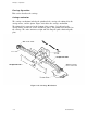
ROM cartridge installation and removal
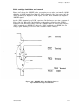
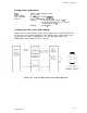
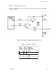
Figure 2-27 shows the -RESET pulse generation process after you install a ROM
cartridge. A LOW signal flows into the -CAR terminal of the gate array (6C, the
-DISC terminal (1) outputs a LOW signal, and the -Rout terminal (2) outputs a
-RESET signal.
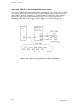
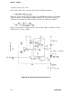
As the -DISC terminal goes LOW, capacitor C26 discharges at a time constant of
R70 x C26 (3). When the C26 discharge reduces the potential at the -THLD
terminal to the threshold voltage Vth, the -RESET signal is canceled (4) and the
-DISC terminal goes HIGH (5). After the -DISC terminal goes HIGH, the Vx
voltage again discharges C31 at a time constant of R69
x
C26 (6).
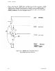
Figure 2-27.
-RESET Pulse Oscillation Process
After ROM Cartridge Installation
LQ-200/AP3000
2-27