
Service manual


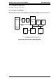


2.3.2 Reset Circuit
Figure 2-11 shows the reset circuit used to reset the controls. Immediately after power on and power off, the
+5 VDC line voltage drops, and the reset IC (IC4, M51953AFP) outputs the reset signal from pin 6 (OUT
port).
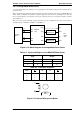
2.3.3 Home Position Sensor Circuit
The home position sensor detects whether the carriage is in the home position. This sensor establishes the
standard carriage drive location. Figure 2-12 is a block diagram of the sensor circuitry. When the carriage is
in the home position, the sensor outputs a HIGH signal to the H8/3003 CPU (pin 25, P95).
Reset IC
M51953AFP
(IC 4)
OUT
+
5 V
IN
6
7
RESET
Figure 2-11. Block Diagram for Reset Circuit
HP Sensor
(CN6, pin 1)
CPU
H8/3003
(IC5)
P95
25
Figure 2-12. Block Diagram for Home Position Sensor
Operating Principles GT-5000 / Action Scanner II Service Manual
2-10 Rev. A