
user manual
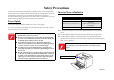
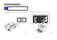
Table Of Contents
- EPSON EPL-6200/EPL-6200L
- Contents
- Product Description
- 1.1 Outline
- 1.2 Basic Specifications
- 1.2.1 Process Specifications
- 1.2.2 Printer Basic Specifications
- 1.2.3 Paper Specification
- 1.2.4 Reliability, Durability, Serviceability
- 1.2.5 Operating Conditions (Including Consumables)
- 1.2.6 Storage and Transport of the Printer Main Unit and Optional Products (Consumables Packaged)
- 1.2.7 Electrical Features
- 1.2.8 Compliance with Standards and Regulations
- 1.2.9 Consumable Components
- 1.3 External Appearance and Parts Name
- 1.4 Controller Specification
- 1.5 Control Panel (EPL-6200)
- 1.6 Control Panel (EPL-6200L)
- 1.7 RAM Expansion
- 1.8 System Requirements (Only for EPL-6200L)
- 1.9 Paper Feed Specifications (Only for EPL-6200L)
- 1.10 Notes on Operation
- 1.11 Status Sheet
- 1.12 Ambient Conditions
- 1.13 Differences in Specifications between Intended Markets
- 1.14 Notes on Installation of Optional Units
- Operating Principles
- 2.1 Overview
- 2.2 Description of Mechanisms
- 2.3 Operating Principles of Electric Circuitry
- Troubleshooting
- 3.1 Overview
- 3.2 Troubleshooting When There is Error Display
- 3.2.1 Fuser warming up problem
- 3.2.2 Fan problem
- 3.2.3 Polygon Motor Error
- 3.2.4 Laser problem
- 3.2.5 High voltage circuit problem
- 3.2.6 Fuser high temperature problem
- 3.2.7 CPU Error
- 3.2.8 Engine Communication Error
- 3.2.9 Fuser low temperature problem
- 3.2.10 Standard RAM Error
- 3.2.11 RAM Error (Slot 0)
- 3.2.12 ROM Checksum Error (Font)
- 3.2.13 ROM Checksum Error (Program)
- 3.2.14 Option ROM Error
- 3.2.15 EEPROM Error
- 3.2.16 Engine Initialization Error
- 3.2.17 Other Hardware Error
- 3.2.18 Software Error
- 3.3 Troubleshooting for Paper Jam
- 3.4 Troubleshooting for Abnormal Operations
- 3.5 Troubleshooting for Electrical Parts
- 3.6 Troubleshooting for Print Quality Problems
- Disassembly and Assembly
- Adjustment
- Maintenance
- Appendix

EPSON EPL-6200/EPL-6200L Revision A
10
3.2.15 EEPROM Error....................................................................................... 114
3.2.16 Engine Initialization Error ...................................................................... 115
3.2.17 Other Hardware Error ............................................................................. 115
3.2.18 Software Error ........................................................................................ 115
3.3 Troubleshooting for Paper Jam ......................................................................... 116
3.3.1 Initial Checking ........................................................................................ 116
3.3.2 Locations of Paper Jam Detection Sensors............................................... 116
3.3.3 Jam Detection Timing / Action to be Taken............................................. 117
3.3.3.1 Paper Feed Area Jam / Paper Transport Area Jam ............................ 117
3.3.3.2 Fuser Area Jam / Paper Eject Area Jam ............................................ 117
3.3.3.3 Transport Area Jam in Duplex Unit (Option) ................................... 118
3.3.3.4 Paper Re-feed Area Jam in Duplex Unit (Option) ............................ 118
3.4 Troubleshooting for Abnormal Operations ....................................................... 119
3.4.1 Power Cannot be Turned ON ................................................................... 119
3.4.2 Electrical Noise......................................................................................... 120
3.5 Troubleshooting for Electrical Parts.................................................................. 121
3.5.1 Checking Method for Electrical Parts....................................................... 121
3.5.2 Sensors...................................................................................................... 121
3.5.3 Switches.................................................................................................... 121
3.5.4 Solenoids................................................................................................... 121
3.5.5 Motors....................................................................................................... 122
3.6 Troubleshooting for Print Quality Problems ..................................................... 123
3.6.1 Blank Print or Solid Black........................................................................ 124
3.6.2 White Out.................................................................................................. 125
3.6.3 Back of Paper Gets Dirty.......................................................................... 125
3.6.4 Low Image Density................................................................................... 126
3.6.5 Foggy Background.................................................................................... 126
3.6.6 White Stripes or White Bands .................................................................. 127
3.6.7 Black Stripes or Black Bands ................................................................... 127
3.6.8 Offset Image ............................................................................................. 128
Chapter 4 Disassembly and Assembly
4.1 Overview ........................................................................................................... 130
4.1.1 Precautions................................................................................................ 130
4.1.2 Tools ......................................................................................................... 131
4.1.3 Screws....................................................................................................... 131
4.1.4 Main Unit Disassembly ............................................................................ 132
4.2 Consumables and Regular Replacement Parts .................................................. 134
4.2.1 Locations of Fuses .................................................................................... 134
4.2.2 Paper Feed Roller ..................................................................................... 134
4.2.3 Developer Cartridge / Photoconductor Unit Replacement ....................... 135
4.2.4 Transfer Roller.......................................................................................... 136
4.3 Removal of Covers............................................................................................ 137
4.3.1 Left Cover................................................................................................. 138
4.3.2 Right Cover............................................................................................... 139
4.3.3 MP Cassette (MP Tray) ............................................................................ 140
4.3.4 Front Cover............................................................................................... 141
4.3.5 Output Tray............................................................................................... 141
4.3.6 Top Cover ................................................................................................. 142
4.3.7 Paper Exit Open/Close Cover................................................................... 142
4.3.8 Paper Exit Cover....................................................................................... 143
4.3.9 Upper Rear Cover..................................................................................... 143
4.3.10 Lower Rear Cover .................................................................................. 144
4.4 Removal and Installation of Circuit Boards ...................................................... 145
4.4.1 Main Board Assy (C533/C534 Main) ...................................................... 146
4.4.1.1 EPL-6200 (C533 Main)..................................................................... 146
4.4.1.2 EPL-6200L (C534 Main) .................................................................. 148
4.4.2 Parallel I/F Board (EPL-6200) ................................................................. 149
4.4.3 USB I/F Board (EPL-6200)...................................................................... 149
4.4.4 Control Panel ............................................................................................ 150
4.4.5 Power Supply Unit (PU1)......................................................................... 151
4.4.6 High Voltage Unit (HV1) ......................................................................... 151
4.5 Removal and Installation of Major Components .............................................. 152
4.5.1 Fuser Unit ................................................................................................. 152
4.5.2 Fuser Unit Disassembly............................................................................ 153
4.5.3 PH Unit ..................................................................................................... 154
4.5.4 Main Motor............................................................................................... 155
4.5.5 Cooling Fan Motor ................................................................................... 155
4.5.6 Paper Tray Empty Sensor (EPL-6200 only)............................................. 156
4.5.7 Paper Feed Solenoid ................................................................................. 157
4.5.8 Paper Feed Clutch Gear............................................................................ 158
4.6 Lower Cassette Unit (Option) ........................................................................... 160
4.6.1 Second Paper Feed Unit ........................................................................... 160
4.6.2 Paper Feed Roller (Lower Cassette)......................................................... 161
4.6.3 Paper Feed Solenoid (Lower Cassette)..................................................... 161
4.6.4 Paper Cassette Unit Control Board........................................................... 162
4.6.5 Paper Size Detect Switch.......................................................................... 162