
user manual
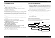

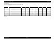
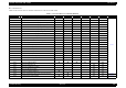
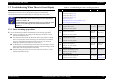
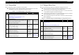
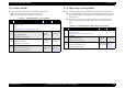
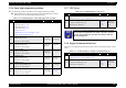
Table Of Contents
- EPSON EPL-6200/EPL-6200L
- Contents
- Product Description
- 1.1 Outline
- 1.2 Basic Specifications
- 1.2.1 Process Specifications
- 1.2.2 Printer Basic Specifications
- 1.2.3 Paper Specification
- 1.2.4 Reliability, Durability, Serviceability
- 1.2.5 Operating Conditions (Including Consumables)
- 1.2.6 Storage and Transport of the Printer Main Unit and Optional Products (Consumables Packaged)
- 1.2.7 Electrical Features
- 1.2.8 Compliance with Standards and Regulations
- 1.2.9 Consumable Components
- 1.3 External Appearance and Parts Name
- 1.4 Controller Specification
- 1.5 Control Panel (EPL-6200)
- 1.6 Control Panel (EPL-6200L)
- 1.7 RAM Expansion
- 1.8 System Requirements (Only for EPL-6200L)
- 1.9 Paper Feed Specifications (Only for EPL-6200L)
- 1.10 Notes on Operation
- 1.11 Status Sheet
- 1.12 Ambient Conditions
- 1.13 Differences in Specifications between Intended Markets
- 1.14 Notes on Installation of Optional Units
- Operating Principles
- 2.1 Overview
- 2.2 Description of Mechanisms
- 2.3 Operating Principles of Electric Circuitry
- Troubleshooting
- 3.1 Overview
- 3.2 Troubleshooting When There is Error Display
- 3.2.1 Fuser warming up problem
- 3.2.2 Fan problem
- 3.2.3 Polygon Motor Error
- 3.2.4 Laser problem
- 3.2.5 High voltage circuit problem
- 3.2.6 Fuser high temperature problem
- 3.2.7 CPU Error
- 3.2.8 Engine Communication Error
- 3.2.9 Fuser low temperature problem
- 3.2.10 Standard RAM Error
- 3.2.11 RAM Error (Slot 0)
- 3.2.12 ROM Checksum Error (Font)
- 3.2.13 ROM Checksum Error (Program)
- 3.2.14 Option ROM Error
- 3.2.15 EEPROM Error
- 3.2.16 Engine Initialization Error
- 3.2.17 Other Hardware Error
- 3.2.18 Software Error
- 3.3 Troubleshooting for Paper Jam
- 3.4 Troubleshooting for Abnormal Operations
- 3.5 Troubleshooting for Electrical Parts
- 3.6 Troubleshooting for Print Quality Problems
- Disassembly and Assembly
- Adjustment
- Maintenance
- Appendix

EPSON EPL-6200/EPL-6200L Revision A
Troubleshooting Troubleshooting When There is Error Display 108
3.2.2 Fan problem
The following condition is handled as a fan problem:
During operation of the Cooling Fan Motor, the lock signal (H or L) has been
maintained for more than the predetermined period of time.
3.2.3 Polygon Motor Error
Any of the following conditions is handled as an polygon motor error:
The lock signal was not detected within the predetermined period of time
counted from one second after start of the polygon motor.
The lock signal was not detected during the period of 1 second counted from
1.5 seconds after emission of the first lock signal.
No lock signal was detected for 0.5 second continuously under the conditions
where the polygon motor was in a steady running state.
The lock signal was kept ON for more than 5 seconds even with the polygon
motor turned OFF.
Table 3-5. Troubleshooting for “Fan problem”
Step Action and Question Yes No
Parts below can be the source of this error (Chapter 4 Disassembly and Assembly)
• Cooling Fan Motor (p.155)
• Main Board Assy (C533/C534 Main) (p.146)
• Power Supply Unit (PU1) (p.151)
1
Cooling Fan Motor 1
Check the connection of the motor connector, and
correct it if any problem is found.
♦Has the error been cleared?
Problem
solved
Go to Step 2
2
Cooling Fan Motor 2
Check the loading on the fan mechanism, and correct
it if any problem is found.
♦Has the error been cleared?
Problem
solved
Go to Step 3
3
Cooling Fan Motor 3
Replace the cooling fan.
♦Has the error been cleared?
Replace the
cooling fan.
Go to Step 4
4
Main Board Assy.
Replace the Main Board Assy.
♦Has the error been cleared?
Replace the
Main Board
Assy.
Go to “3.4.2
Electrical
Noise” (p.120)
Table 3-6. Troubleshooting forTroubleshooting for “Polygon Motor Error”
Step Action and Question Yes No
Parts below can be the source of this error (Chapter 4 Disassembly and Assembly)
• PH Unit (p.154)
• FFC
• Main Board Assy (C533/C534 Main) (p.146)
1
Connection with connectors
Check the connection of the cable, and correct it if
any problem is found.
♦Has the error been cleared?
Problem
solved
Go to Step 2
2
PH unit
Replace the PH unit.
♦Has the error been cleared?
Replace the
PH unit.
Go to Step 3
3
Main Board Assy.
Replace the Main Board Assy.
♦Has the error been cleared?
Replace the
Main Board
Assy.
Go to “3.4.2
Electrical
Noise” (p.120)