
user manual

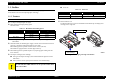
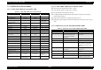
Table Of Contents
- EPSON EPL-6200/EPL-6200L
- Contents
- Product Description
- 1.1 Outline
- 1.2 Basic Specifications
- 1.2.1 Process Specifications
- 1.2.2 Printer Basic Specifications
- 1.2.3 Paper Specification
- 1.2.4 Reliability, Durability, Serviceability
- 1.2.5 Operating Conditions (Including Consumables)
- 1.2.6 Storage and Transport of the Printer Main Unit and Optional Products (Consumables Packaged)
- 1.2.7 Electrical Features
- 1.2.8 Compliance with Standards and Regulations
- 1.2.9 Consumable Components
- 1.3 External Appearance and Parts Name
- 1.4 Controller Specification
- 1.5 Control Panel (EPL-6200)
- 1.6 Control Panel (EPL-6200L)
- 1.7 RAM Expansion
- 1.8 System Requirements (Only for EPL-6200L)
- 1.9 Paper Feed Specifications (Only for EPL-6200L)
- 1.10 Notes on Operation
- 1.11 Status Sheet
- 1.12 Ambient Conditions
- 1.13 Differences in Specifications between Intended Markets
- 1.14 Notes on Installation of Optional Units
- Operating Principles
- 2.1 Overview
- 2.2 Description of Mechanisms
- 2.3 Operating Principles of Electric Circuitry
- Troubleshooting
- 3.1 Overview
- 3.2 Troubleshooting When There is Error Display
- 3.2.1 Fuser warming up problem
- 3.2.2 Fan problem
- 3.2.3 Polygon Motor Error
- 3.2.4 Laser problem
- 3.2.5 High voltage circuit problem
- 3.2.6 Fuser high temperature problem
- 3.2.7 CPU Error
- 3.2.8 Engine Communication Error
- 3.2.9 Fuser low temperature problem
- 3.2.10 Standard RAM Error
- 3.2.11 RAM Error (Slot 0)
- 3.2.12 ROM Checksum Error (Font)
- 3.2.13 ROM Checksum Error (Program)
- 3.2.14 Option ROM Error
- 3.2.15 EEPROM Error
- 3.2.16 Engine Initialization Error
- 3.2.17 Other Hardware Error
- 3.2.18 Software Error
- 3.3 Troubleshooting for Paper Jam
- 3.4 Troubleshooting for Abnormal Operations
- 3.5 Troubleshooting for Electrical Parts
- 3.6 Troubleshooting for Print Quality Problems
- Disassembly and Assembly
- Adjustment
- Maintenance
- Appendix

EPSON EPL-6200/EPL-6200L Revision A
11
4.7 Duplex Unit (Option) ........................................................................................ 163
4.7.1 Right Cover............................................................................................... 163
4.7.2 Left Cover................................................................................................. 163
4.7.3 Duplex Unit Control Board ...................................................................... 163
4.7.4 Duplex Unit Inversion Motor ................................................................... 164
4.7.5 Duplex Unit Transport Motor................................................................... 164
4.7.6 Duplex Unit Skew Correction Solenoid ................................................... 164
Chapter 5 Adjustment
5.1 Overview ........................................................................................................... 166
5.2 USB ID Input..................................................................................................... 167
5.2.1 Installation Procedure for Program........................................................... 167
5.2.2 Procedure for Program Operation............................................................. 167
5.3 Feed Registration Adjustment ........................................................................... 169
5.3.1 Preparation................................................................................................ 169
5.3.2 Adjustment................................................................................................ 169
Chapter 6 Maintenance
6.1 Overview ........................................................................................................... 173
6.1.1 Cleaning.................................................................................................... 173
6.1.2 Maintenance.............................................................................................. 173
6.1.3 Cleaning of Paper Feed Rollers ................................................................ 174
Chapter 7 Appendix
7.1 Connectors......................................................................................................... 176
7.1.1 Connectors on Main Board Assy (EPL-6200).......................................... 176
7.1.2 Connectors on Main Board Assy (EPL-6200L) ....................................... 177
7.1.3 Connector Assignment Diagram (Overall) ............................................... 178
7.2 Circuit Diagrams ............................................................................................... 179
7.3 Exploded Diagrams ........................................................................................... 186
7.4 ASP List............................................................................................................. 197