
user manual
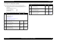
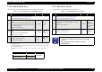
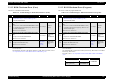
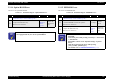
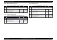
Table Of Contents
- EPSON EPL-6200/EPL-6200L
- Contents
- Product Description
- 1.1 Outline
- 1.2 Basic Specifications
- 1.2.1 Process Specifications
- 1.2.2 Printer Basic Specifications
- 1.2.3 Paper Specification
- 1.2.4 Reliability, Durability, Serviceability
- 1.2.5 Operating Conditions (Including Consumables)
- 1.2.6 Storage and Transport of the Printer Main Unit and Optional Products (Consumables Packaged)
- 1.2.7 Electrical Features
- 1.2.8 Compliance with Standards and Regulations
- 1.2.9 Consumable Components
- 1.3 External Appearance and Parts Name
- 1.4 Controller Specification
- 1.5 Control Panel (EPL-6200)
- 1.6 Control Panel (EPL-6200L)
- 1.7 RAM Expansion
- 1.8 System Requirements (Only for EPL-6200L)
- 1.9 Paper Feed Specifications (Only for EPL-6200L)
- 1.10 Notes on Operation
- 1.11 Status Sheet
- 1.12 Ambient Conditions
- 1.13 Differences in Specifications between Intended Markets
- 1.14 Notes on Installation of Optional Units
- Operating Principles
- 2.1 Overview
- 2.2 Description of Mechanisms
- 2.3 Operating Principles of Electric Circuitry
- Troubleshooting
- 3.1 Overview
- 3.2 Troubleshooting When There is Error Display
- 3.2.1 Fuser warming up problem
- 3.2.2 Fan problem
- 3.2.3 Polygon Motor Error
- 3.2.4 Laser problem
- 3.2.5 High voltage circuit problem
- 3.2.6 Fuser high temperature problem
- 3.2.7 CPU Error
- 3.2.8 Engine Communication Error
- 3.2.9 Fuser low temperature problem
- 3.2.10 Standard RAM Error
- 3.2.11 RAM Error (Slot 0)
- 3.2.12 ROM Checksum Error (Font)
- 3.2.13 ROM Checksum Error (Program)
- 3.2.14 Option ROM Error
- 3.2.15 EEPROM Error
- 3.2.16 Engine Initialization Error
- 3.2.17 Other Hardware Error
- 3.2.18 Software Error
- 3.3 Troubleshooting for Paper Jam
- 3.4 Troubleshooting for Abnormal Operations
- 3.5 Troubleshooting for Electrical Parts
- 3.6 Troubleshooting for Print Quality Problems
- Disassembly and Assembly
- Adjustment
- Maintenance
- Appendix
EPSON EPL-6200/EPL-6200L Revision A
Troubleshooting Troubleshooting When There is Error Display 111
3.2.9 Fuser low temperature problem
The following condition is handled as a fuser low temperature problem:
During temperature control, the thermistor detected temperature was kept
below the preset temperature over the predetermined period of time
continuously.
The preset temperature is as follows:
In 600 dpi printing mode: 140°C
In 1200 dpi printing mode: 110°C
In standby mode: 70°C
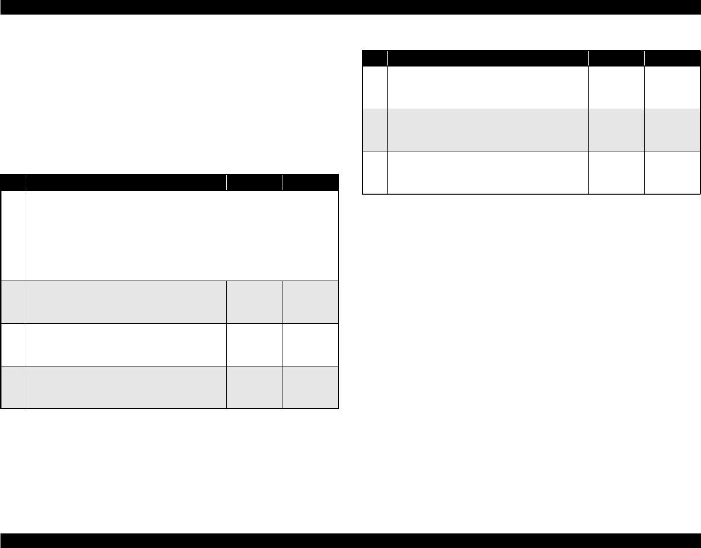
Table 3-12. Troubleshooting for “Fuser low temperature problem”
Step Action and Question Yes No
Parts below can be the source of this error (Chapter 4 Disassembly and Assembly)
• Thermistor (TH1) (p.153)
• Heater lamp (H1) (p.153)
• Thermostat (TS1) (p.153)
• Fuser Unit (p.152)
• Main Board Assy (C533/C534 Main) (p.146)
• Power Supply Unit (PU1) (p.151)
1
Fuser unit
Replace the fuser unit.
♦Has the error been cleared?
Go to Step 2 Go to Step 5
2
Thermistor (TH1)
Replace the thermistor.
♦Has the error been cleared?
Replace the
thermistor.
Go to Step 3
3
Heater lamp (H1)
Replace the heater lamp.
♦Has the error been cleared?
Replace the
heater lamp.
Go to Step 4
4
Thermostat (TS1)
Replace the thermostat.
♦Has the error been cleared?
Replace the
thermostat.
Replace the
fuser unit.
5
Main Board Assy.
Replace the Main Board Assy.
♦Has the error been cleared?
Replace the
Main Board
Assy.
Go to Step 6
6
Power supply unit
Replace the power supply unit.
♦Has the error been cleared?
Replace the
power supply
unit.
Go to “3.4.2
Electrical
Noise” (p.120)
Table 3-12. Troubleshooting for “Fuser low temperature problem” (continued)
Step Action and Question Yes No