
user manual
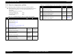
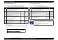
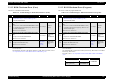
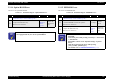
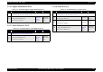
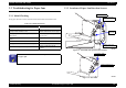
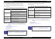
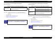
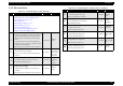
Table Of Contents
- EPSON EPL-6200/EPL-6200L
- Contents
- Product Description
- 1.1 Outline
- 1.2 Basic Specifications
- 1.2.1 Process Specifications
- 1.2.2 Printer Basic Specifications
- 1.2.3 Paper Specification
- 1.2.4 Reliability, Durability, Serviceability
- 1.2.5 Operating Conditions (Including Consumables)
- 1.2.6 Storage and Transport of the Printer Main Unit and Optional Products (Consumables Packaged)
- 1.2.7 Electrical Features
- 1.2.8 Compliance with Standards and Regulations
- 1.2.9 Consumable Components
- 1.3 External Appearance and Parts Name
- 1.4 Controller Specification
- 1.5 Control Panel (EPL-6200)
- 1.6 Control Panel (EPL-6200L)
- 1.7 RAM Expansion
- 1.8 System Requirements (Only for EPL-6200L)
- 1.9 Paper Feed Specifications (Only for EPL-6200L)
- 1.10 Notes on Operation
- 1.11 Status Sheet
- 1.12 Ambient Conditions
- 1.13 Differences in Specifications between Intended Markets
- 1.14 Notes on Installation of Optional Units
- Operating Principles
- 2.1 Overview
- 2.2 Description of Mechanisms
- 2.3 Operating Principles of Electric Circuitry
- Troubleshooting
- 3.1 Overview
- 3.2 Troubleshooting When There is Error Display
- 3.2.1 Fuser warming up problem
- 3.2.2 Fan problem
- 3.2.3 Polygon Motor Error
- 3.2.4 Laser problem
- 3.2.5 High voltage circuit problem
- 3.2.6 Fuser high temperature problem
- 3.2.7 CPU Error
- 3.2.8 Engine Communication Error
- 3.2.9 Fuser low temperature problem
- 3.2.10 Standard RAM Error
- 3.2.11 RAM Error (Slot 0)
- 3.2.12 ROM Checksum Error (Font)
- 3.2.13 ROM Checksum Error (Program)
- 3.2.14 Option ROM Error
- 3.2.15 EEPROM Error
- 3.2.16 Engine Initialization Error
- 3.2.17 Other Hardware Error
- 3.2.18 Software Error
- 3.3 Troubleshooting for Paper Jam
- 3.4 Troubleshooting for Abnormal Operations
- 3.5 Troubleshooting for Electrical Parts
- 3.6 Troubleshooting for Print Quality Problems
- Disassembly and Assembly
- Adjustment
- Maintenance
- Appendix

EPSON EPL-6200/EPL-6200L Revision A
Troubleshooting Troubleshooting for Paper Jam 117
3.3.3 Jam Detection Timing / Action to be Taken
3.3.3.1 Paper Feed Area Jam / Paper Transport Area Jam
Detection Timing
Solution: Check the “Initial Check Items” (p.116) first and then replace the
following components in the order named with new ones and repeat
checking.
1. Paper Feed Solenoid
(p.157)
2. Paper Feed Roller (Lower Cassette) (p.161)
3. Paper Feed Sensor (S1)
4. Eject Sensor (PS3)
5.
Main Board Assy (C533/C534 Main) (p.146)
3.3.3.2 Fuser Area Jam / Paper Eject Area Jam
Detection Timing
Solution: Check the “Initial Check Items” (p.116) first and then replace the
following components in the order named with new ones and repeat
checking.
1. Paper Feed Sensor (S1)
2. Eject Sensor (PS3)
3.
Main Board Assy (C533/C534 Main) (p.146)
Table 3-23. Paper Feed Area Jam / Paper Transport Area Jam
Category Explanation
Jam detection in paper feed
area
After start of paper feeding, the Paper Feed Sensor turned ON
earlier than the passage of the predetermined time.
The Paper Feed Sensor did not turn ON even after the passage of
the predetermined period of time from start of paper feeding.
Paper eject area
After the Paper Feed Sensor turned ON, it turned OFF earlier than
the passage of the predetermined time.
The Paper Feed Sensor did not turn OFF even after the passage of
the predetermined period of time from turning ON of the Paper
Feed Sensor.
Remaining paper detection
in paper feed area
After start of paper feeding, paper transport stopped before the
Paper Feed Sensor turned OFF.
Remaining paper detection
in paper eject area
The Paper Feed Sensor was ON at turning on of the Main Switch,
at opening and closing of the front door, at occurrence of a paper
jam or at stop of paper transport.
At stop of paper transport, there is paper between the Paper Feed
Sensor and the Paper Eject Sensor.
C H E C K
P O I N T
Before replacing any electrical part, check to see if the part in
question is defective or not by consulting “3.5 Troubleshooting for
Electrical Parts”
(p.121). Then replace the part, if necessary.
Table 3-24. Fuser Area Jam / Paper Eject Area Jam
Category Explanation
Remaining paper
detection in fuser area
The light to the Paper Eject Sensor was transmitted at turning on of
the Main Switch, at opening and closing of the front door, at
occurrence of a paper jam or at stop of paper transport.
Paper eject area
The light to the Paper Eject Sensor was transmitted earlier than the
passage of the predetermined period of time from the turning on of
the Paper Feed Sensor.
The light to the Paper Eject Sensor was not transmitted even after
the passage of the predetermined period of time from the turning on
of the Paper Feed Sensor.
Paper eject area jam
The light to the Paper Eject Sensor was intercepted earlier than the
passage of the predetermined period of time from the turning off of
the Paper Feed Sensor.
C H E C K
P O I N T
Before replacing any electrical part, check to see if the part in
question is defective or not by consulting “3.5 Troubleshooting for
Electrical Parts”
(p.121). Then replace the part, if necessary.