
user manual
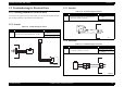
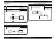

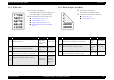
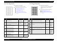
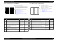


Table Of Contents
- EPSON EPL-6200/EPL-6200L
- Contents
- Product Description
- 1.1 Outline
- 1.2 Basic Specifications
- 1.2.1 Process Specifications
- 1.2.2 Printer Basic Specifications
- 1.2.3 Paper Specification
- 1.2.4 Reliability, Durability, Serviceability
- 1.2.5 Operating Conditions (Including Consumables)
- 1.2.6 Storage and Transport of the Printer Main Unit and Optional Products (Consumables Packaged)
- 1.2.7 Electrical Features
- 1.2.8 Compliance with Standards and Regulations
- 1.2.9 Consumable Components
- 1.3 External Appearance and Parts Name
- 1.4 Controller Specification
- 1.5 Control Panel (EPL-6200)
- 1.6 Control Panel (EPL-6200L)
- 1.7 RAM Expansion
- 1.8 System Requirements (Only for EPL-6200L)
- 1.9 Paper Feed Specifications (Only for EPL-6200L)
- 1.10 Notes on Operation
- 1.11 Status Sheet
- 1.12 Ambient Conditions
- 1.13 Differences in Specifications between Intended Markets
- 1.14 Notes on Installation of Optional Units
- Operating Principles
- 2.1 Overview
- 2.2 Description of Mechanisms
- 2.3 Operating Principles of Electric Circuitry
- Troubleshooting
- 3.1 Overview
- 3.2 Troubleshooting When There is Error Display
- 3.2.1 Fuser warming up problem
- 3.2.2 Fan problem
- 3.2.3 Polygon Motor Error
- 3.2.4 Laser problem
- 3.2.5 High voltage circuit problem
- 3.2.6 Fuser high temperature problem
- 3.2.7 CPU Error
- 3.2.8 Engine Communication Error
- 3.2.9 Fuser low temperature problem
- 3.2.10 Standard RAM Error
- 3.2.11 RAM Error (Slot 0)
- 3.2.12 ROM Checksum Error (Font)
- 3.2.13 ROM Checksum Error (Program)
- 3.2.14 Option ROM Error
- 3.2.15 EEPROM Error
- 3.2.16 Engine Initialization Error
- 3.2.17 Other Hardware Error
- 3.2.18 Software Error
- 3.3 Troubleshooting for Paper Jam
- 3.4 Troubleshooting for Abnormal Operations
- 3.5 Troubleshooting for Electrical Parts
- 3.6 Troubleshooting for Print Quality Problems
- Disassembly and Assembly
- Adjustment
- Maintenance
- Appendix

EPSON EPL-6200/EPL-6200L Revision A
Troubleshooting Troubleshooting for Print Quality Problems 127
3.6.6 White Stripes or White Bands 3.6.7 Black Stripes or Black Bands
Description of the problem:
There are light or completely white bands in
the printed image. These bands are running
parallel with paper-feed direction over a wide
area.
Parts that may be the source of this error
Transfer Roller (p.136)
Photoconductor Unit (p.135)
Fuser Unit (p.152)
Main Board Assy (C533/C534 Main)
(p.146)
Step Action and Question Yes No
1
Transfer roller
♦Is the Transfer Roller dented, scratched or soiled?
Replace the
transfer roller.
Go to Step 2
2
OPC drum
♦Is the OPC drum is scratched, seamed or soiled?
Replace the
Photoconductor
Unit.
Go to Step 3
3
Fusing roller
♦Is the fusing roller scratched or soiled?
Replace the
Fuser Unit
(fusing roller).
Go to Step 4
4
PH window soiled
♦Is the surface of the PH window soiled?
Clean Go to Step 5
5
♦ Was the problem solved after any of the Steps
above? Problem solved
Replace the
Main Board
Assy.
Description of the problem:
Black stripes or bands are running parallel
with the paper-feed direction.
Parts that may be the source of this error
Photoconductor Unit (p.135)
Fuser Unit (p.152)
Main Board Assy (C533/C534 Main)
(p.146)
Step Action and Question Yes No
1
Inside of the printer
♦Is the paper path soiled with toner?
Clean Go to Step 2
2
OPC drum
♦Is the OPC drum is scratched, seamed or soiled?
Replace the
Photoconductor
Unit.
Go to Step 3
3
Fusing roller
♦Is the fusing roller scratched or soiled?
Replace the
Fuser Unit
(fusing roller).
Go to Step 4
4
♦Was the problem solved after any of the Steps
above? Problem solved
Replace the
Main Board
Assy.