
user manual


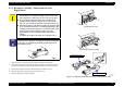

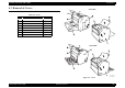

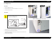

Table Of Contents
- EPSON EPL-6200/EPL-6200L
- Contents
- Product Description
- 1.1 Outline
- 1.2 Basic Specifications
- 1.2.1 Process Specifications
- 1.2.2 Printer Basic Specifications
- 1.2.3 Paper Specification
- 1.2.4 Reliability, Durability, Serviceability
- 1.2.5 Operating Conditions (Including Consumables)
- 1.2.6 Storage and Transport of the Printer Main Unit and Optional Products (Consumables Packaged)
- 1.2.7 Electrical Features
- 1.2.8 Compliance with Standards and Regulations
- 1.2.9 Consumable Components
- 1.3 External Appearance and Parts Name
- 1.4 Controller Specification
- 1.5 Control Panel (EPL-6200)
- 1.6 Control Panel (EPL-6200L)
- 1.7 RAM Expansion
- 1.8 System Requirements (Only for EPL-6200L)
- 1.9 Paper Feed Specifications (Only for EPL-6200L)
- 1.10 Notes on Operation
- 1.11 Status Sheet
- 1.12 Ambient Conditions
- 1.13 Differences in Specifications between Intended Markets
- 1.14 Notes on Installation of Optional Units
- Operating Principles
- 2.1 Overview
- 2.2 Description of Mechanisms
- 2.3 Operating Principles of Electric Circuitry
- Troubleshooting
- 3.1 Overview
- 3.2 Troubleshooting When There is Error Display
- 3.2.1 Fuser warming up problem
- 3.2.2 Fan problem
- 3.2.3 Polygon Motor Error
- 3.2.4 Laser problem
- 3.2.5 High voltage circuit problem
- 3.2.6 Fuser high temperature problem
- 3.2.7 CPU Error
- 3.2.8 Engine Communication Error
- 3.2.9 Fuser low temperature problem
- 3.2.10 Standard RAM Error
- 3.2.11 RAM Error (Slot 0)
- 3.2.12 ROM Checksum Error (Font)
- 3.2.13 ROM Checksum Error (Program)
- 3.2.14 Option ROM Error
- 3.2.15 EEPROM Error
- 3.2.16 Engine Initialization Error
- 3.2.17 Other Hardware Error
- 3.2.18 Software Error
- 3.3 Troubleshooting for Paper Jam
- 3.4 Troubleshooting for Abnormal Operations
- 3.5 Troubleshooting for Electrical Parts
- 3.6 Troubleshooting for Print Quality Problems
- Disassembly and Assembly
- Adjustment
- Maintenance
- Appendix

EPSON EPL-6200/EPL-6200L Revision A
Disassembly and Assembly Overview 131
4.1.2 Tools
Use only specified tools to avoid damaging the printer.
4.1.3 Screws
W A R N I N G
Avant de commencer, assurez vous que l’imprimante soit eteinte et
que le cordon d’alimentation soit debranche.
C A U T I O N
Use only recommended tools for disassembling, assembling or
adjusting the printer.
Observe the tightning torque when fixing screws.
Apply lubricants and adhesives as specified. (See Chapter 6 for
details.)
Make the specified adjustments when you disassemble the
printer. (See Chapter 5 for details.)
Take following precautions when connecting or disconnecting
flat cables.
If the Photoconductor Unit (Drum Cartridge) is exposed to light
for an extended period of time, it can undergo light fatigue, thus
resulting in degradation of image. To avoid such trouble, when
you have taken out the Imaging Cartridge, protect the
Photoconductor Unit by covering it with a clean cloth for
shading.
Name Commercial Availability Code
Phillips screwdriver No. 1 Available B743800100
Phillips screwdriver No. 2 Available B743800500
Mini Phillips screwdriver Available -
Slotted screwdriver Available B743000100
Table 4-1. Screws
Ref. No.
Nominal
Size
Name and Specification Appearance
1305
3x6
+ Pan Head Screw - with Spring
Washer and Plain Washer
(Sems)
1308 3x8
3501
3x6
+ Cup Screw
3504 3x8
3907 3x8 + Bind B-tite Screw
1112 3x6 + Bind S-tite Screw
3704 3x8 + Cup B-tite Screw