
user manual


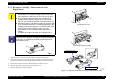

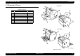

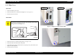

Table Of Contents
- EPSON EPL-6200/EPL-6200L
- Contents
- Product Description
- 1.1 Outline
- 1.2 Basic Specifications
- 1.2.1 Process Specifications
- 1.2.2 Printer Basic Specifications
- 1.2.3 Paper Specification
- 1.2.4 Reliability, Durability, Serviceability
- 1.2.5 Operating Conditions (Including Consumables)
- 1.2.6 Storage and Transport of the Printer Main Unit and Optional Products (Consumables Packaged)
- 1.2.7 Electrical Features
- 1.2.8 Compliance with Standards and Regulations
- 1.2.9 Consumable Components
- 1.3 External Appearance and Parts Name
- 1.4 Controller Specification
- 1.5 Control Panel (EPL-6200)
- 1.6 Control Panel (EPL-6200L)
- 1.7 RAM Expansion
- 1.8 System Requirements (Only for EPL-6200L)
- 1.9 Paper Feed Specifications (Only for EPL-6200L)
- 1.10 Notes on Operation
- 1.11 Status Sheet
- 1.12 Ambient Conditions
- 1.13 Differences in Specifications between Intended Markets
- 1.14 Notes on Installation of Optional Units
- Operating Principles
- 2.1 Overview
- 2.2 Description of Mechanisms
- 2.3 Operating Principles of Electric Circuitry
- Troubleshooting
- 3.1 Overview
- 3.2 Troubleshooting When There is Error Display
- 3.2.1 Fuser warming up problem
- 3.2.2 Fan problem
- 3.2.3 Polygon Motor Error
- 3.2.4 Laser problem
- 3.2.5 High voltage circuit problem
- 3.2.6 Fuser high temperature problem
- 3.2.7 CPU Error
- 3.2.8 Engine Communication Error
- 3.2.9 Fuser low temperature problem
- 3.2.10 Standard RAM Error
- 3.2.11 RAM Error (Slot 0)
- 3.2.12 ROM Checksum Error (Font)
- 3.2.13 ROM Checksum Error (Program)
- 3.2.14 Option ROM Error
- 3.2.15 EEPROM Error
- 3.2.16 Engine Initialization Error
- 3.2.17 Other Hardware Error
- 3.2.18 Software Error
- 3.3 Troubleshooting for Paper Jam
- 3.4 Troubleshooting for Abnormal Operations
- 3.5 Troubleshooting for Electrical Parts
- 3.6 Troubleshooting for Print Quality Problems
- Disassembly and Assembly
- Adjustment
- Maintenance
- Appendix
EPSON EPL-6200/EPL-6200L Revision A
Disassembly and Assembly Overview 132
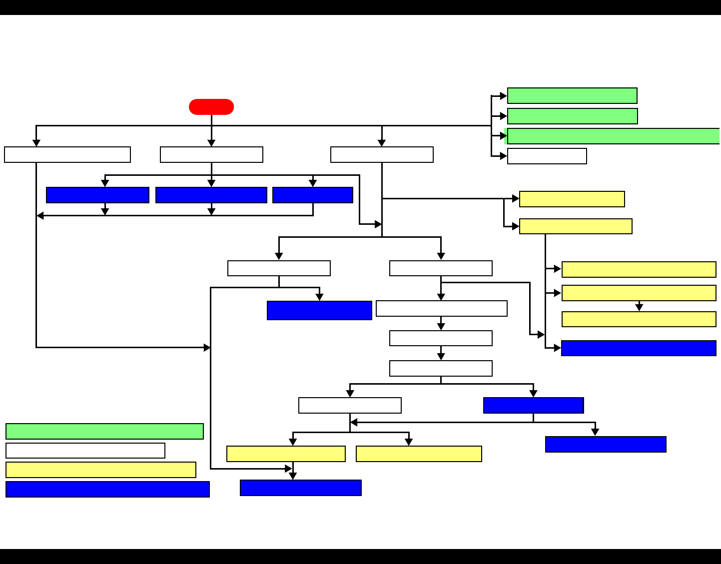
4.1.4 Main Unit Disassembly
The flowchart below shows step-by-step disassembly procedure. When disassembling each component, refer to the page number shown in the figure.
Flowchart 4-1. Disassembly Flowchart
Right Cover (p.139)
Top Cover (p.142)
Main Board Assy (C533/C534 Main) (p.146)
Control Panel (p.150)
Protection Sheet Metal (p146)
Front Cover (p.141)
Left Cover (p.138)
Cooling Fan Motor (p.155) Main Motor (p.155)Paper Feed Solenoid (p.157)
MP Cassette (MP Tray) (p.140)
PH Unit (p.154)
Paper Exit Open/Close Cover (p.142)
Paper Exit Cover (p.143)
Upper Rear Cover (p.143)
Lower Rear Cover (p.144) Fuser Unit (p.152)
High Voltage Unit (HV1) (p.151)Power Supply Unit (PU1) (p.151)
Paper Feed Clutch Gear (p.158)
Fuser Unit Disassembly (p.153)
Paper Tray Empty Sensor
(EPL-6200 only) (p.156)
4.3 Removal of Covers (p137)
4.4 Removal and Installation of Circuit Boards (p145)
4.5 Removal and Installation of Major Components (p152)
4.2 Consumables and Regular Replacement Parts (p134)
START
Paper Feed Roller (p.134)
Transfer Roller (p.136)
Developer Cartridge / Photoconductor Unit Replacement (p.
1
Output Tray (p.141)
Parallel I/F Board (EPL-6200) (p.149)
USB I/F Board (EPL-6200) (p.149)