
user manual


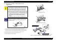

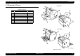

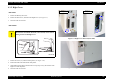

Table Of Contents
- EPSON EPL-6200/EPL-6200L
- Contents
- Product Description
- 1.1 Outline
- 1.2 Basic Specifications
- 1.2.1 Process Specifications
- 1.2.2 Printer Basic Specifications
- 1.2.3 Paper Specification
- 1.2.4 Reliability, Durability, Serviceability
- 1.2.5 Operating Conditions (Including Consumables)
- 1.2.6 Storage and Transport of the Printer Main Unit and Optional Products (Consumables Packaged)
- 1.2.7 Electrical Features
- 1.2.8 Compliance with Standards and Regulations
- 1.2.9 Consumable Components
- 1.3 External Appearance and Parts Name
- 1.4 Controller Specification
- 1.5 Control Panel (EPL-6200)
- 1.6 Control Panel (EPL-6200L)
- 1.7 RAM Expansion
- 1.8 System Requirements (Only for EPL-6200L)
- 1.9 Paper Feed Specifications (Only for EPL-6200L)
- 1.10 Notes on Operation
- 1.11 Status Sheet
- 1.12 Ambient Conditions
- 1.13 Differences in Specifications between Intended Markets
- 1.14 Notes on Installation of Optional Units
- Operating Principles
- 2.1 Overview
- 2.2 Description of Mechanisms
- 2.3 Operating Principles of Electric Circuitry
- Troubleshooting
- 3.1 Overview
- 3.2 Troubleshooting When There is Error Display
- 3.2.1 Fuser warming up problem
- 3.2.2 Fan problem
- 3.2.3 Polygon Motor Error
- 3.2.4 Laser problem
- 3.2.5 High voltage circuit problem
- 3.2.6 Fuser high temperature problem
- 3.2.7 CPU Error
- 3.2.8 Engine Communication Error
- 3.2.9 Fuser low temperature problem
- 3.2.10 Standard RAM Error
- 3.2.11 RAM Error (Slot 0)
- 3.2.12 ROM Checksum Error (Font)
- 3.2.13 ROM Checksum Error (Program)
- 3.2.14 Option ROM Error
- 3.2.15 EEPROM Error
- 3.2.16 Engine Initialization Error
- 3.2.17 Other Hardware Error
- 3.2.18 Software Error
- 3.3 Troubleshooting for Paper Jam
- 3.4 Troubleshooting for Abnormal Operations
- 3.5 Troubleshooting for Electrical Parts
- 3.6 Troubleshooting for Print Quality Problems
- Disassembly and Assembly
- Adjustment
- Maintenance
- Appendix
EPSON EPL-6200/EPL-6200L Revision A
Disassembly and Assembly Consumables and Regular Replacement Parts 135
4.2.3 Developer Cartridge / Photoconductor Unit
Replacement
1. Open the Front Cover, and take out the Imaging Cartridge from the printer.
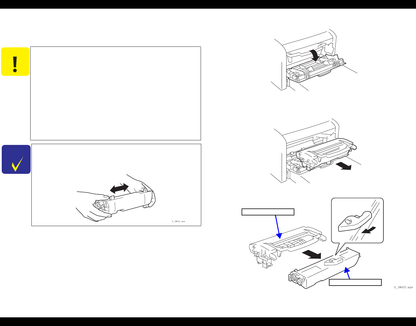
2. Turn the lever of the Developer Cartridge (toner cartridge) in the direction as shown
and separate the Developer Cartridge and the Photoconductor Unit from each other.
3. Replace the Developer Cartridge or Photoconductor Unit with a new one.
4. Install the Developer Cartridge on the Photoconductor Unit.
5. Install the Imaging Cartridge in the printer.
Figure 4-3. Replacing the Developer Cartridge / Photoconductor Unit
C A U T I O N
When you put the Developer Cartridge (toner cartridge) and
Photoconductor Unit (Drum Cartridge) separated from each
other on the floor or table, take care not to let toner fly apart.
If you put the Developer Cartridge (toner cartridge) in an
upright position and shake it strongly, toner may come out.
Take care not to handle the Developer Cartridge in such a way.
If the Photoconductor Unit (Drum Cartridge) is exposed to light
for an extended period of time, it can undergo light fatigue, thus
resulting in degradation of image. To avoid such trouble, when
you have taken out the Imaging Cartridge, protect the
Photoconductor Unit by covering it with a clean cloth for
shading.
In addition, do not this work under any strong light source.
C H E C K
P O I N T
For replacing the Developer Cartridge (toner cartridge), swing
adequately the new Developer Cartridge horizontally beforehand to
stir the toner. (To minimize the possibility of light fatigue of the
Photoconductor Unit.)
Photoconductor Unit
Developer Cartridge
Opening the Front Cover
Removing the Imaging Cartridge