
user manual
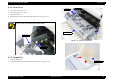
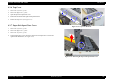
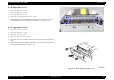
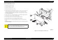
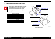
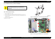
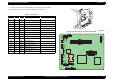
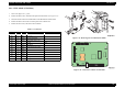
Table Of Contents
- EPSON EPL-6200/EPL-6200L
- Contents
- Product Description
- 1.1 Outline
- 1.2 Basic Specifications
- 1.2.1 Process Specifications
- 1.2.2 Printer Basic Specifications
- 1.2.3 Paper Specification
- 1.2.4 Reliability, Durability, Serviceability
- 1.2.5 Operating Conditions (Including Consumables)
- 1.2.6 Storage and Transport of the Printer Main Unit and Optional Products (Consumables Packaged)
- 1.2.7 Electrical Features
- 1.2.8 Compliance with Standards and Regulations
- 1.2.9 Consumable Components
- 1.3 External Appearance and Parts Name
- 1.4 Controller Specification
- 1.5 Control Panel (EPL-6200)
- 1.6 Control Panel (EPL-6200L)
- 1.7 RAM Expansion
- 1.8 System Requirements (Only for EPL-6200L)
- 1.9 Paper Feed Specifications (Only for EPL-6200L)
- 1.10 Notes on Operation
- 1.11 Status Sheet
- 1.12 Ambient Conditions
- 1.13 Differences in Specifications between Intended Markets
- 1.14 Notes on Installation of Optional Units
- Operating Principles
- 2.1 Overview
- 2.2 Description of Mechanisms
- 2.3 Operating Principles of Electric Circuitry
- Troubleshooting
- 3.1 Overview
- 3.2 Troubleshooting When There is Error Display
- 3.2.1 Fuser warming up problem
- 3.2.2 Fan problem
- 3.2.3 Polygon Motor Error
- 3.2.4 Laser problem
- 3.2.5 High voltage circuit problem
- 3.2.6 Fuser high temperature problem
- 3.2.7 CPU Error
- 3.2.8 Engine Communication Error
- 3.2.9 Fuser low temperature problem
- 3.2.10 Standard RAM Error
- 3.2.11 RAM Error (Slot 0)
- 3.2.12 ROM Checksum Error (Font)
- 3.2.13 ROM Checksum Error (Program)
- 3.2.14 Option ROM Error
- 3.2.15 EEPROM Error
- 3.2.16 Engine Initialization Error
- 3.2.17 Other Hardware Error
- 3.2.18 Software Error
- 3.3 Troubleshooting for Paper Jam
- 3.4 Troubleshooting for Abnormal Operations
- 3.5 Troubleshooting for Electrical Parts
- 3.6 Troubleshooting for Print Quality Problems
- Disassembly and Assembly
- Adjustment
- Maintenance
- Appendix
EPSON EPL-6200/EPL-6200L Revision A
Disassembly and Assembly Removal of Covers 144
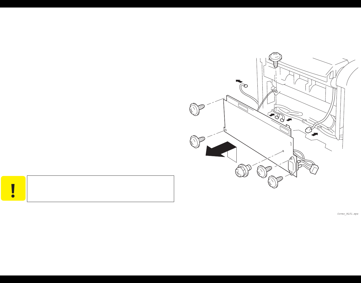
4.3.10 Lower Rear Cover
1.
Remove the Left Cover. (p.138)
2.
Remove the Right Cover. (p.139)
3.
Remove the Top Cover. (p.142)
4.
Remove the Paper Exit Cover. (p.143)
5.
Remove the Upper Rear Cover. (p.143)
6. Remove the two screws securing the Lower Rear Cover, the one screw on the IF side
securing the High Voltage Unit (HV1) and the two screws securing the AC Inlet.
7. Release the two hooks by lifting the Lower Rear Cover, and remove the Lower Rear
Cover from the printer body.
8. Remove the one screw securing the grounding wire on the High Voltage Unit (HV1).
9. Disconnect the connector (CN807) on the Main Board.
10. Disconnect the connector (CN3) on the Power Supply Unit (PU1).
11. Disconnect the connector (CN1) on the High Voltage Unit (HV1).
12. Remove the one screw securing the grounding wire of the AC Inlet to the printer
frame.
13. Remove the Power Switch at the side of the printer body while releasing the right and
left hooks (two hooks).
Figure 4-19. Removing the Lower Rear Cover
C A U T I O N
On the Rear cover, the High Voltage Unit (HV1) and Power Supply
Unit (PU1) are installed and thus many connectors are connected.
Therefore, take due care when removing the Rear Cover.