
user manual
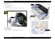
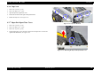
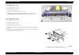
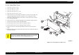
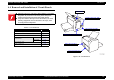
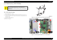
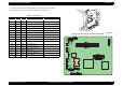
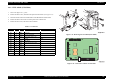
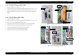
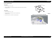
Table Of Contents
- EPSON EPL-6200/EPL-6200L
- Contents
- Product Description
- 1.1 Outline
- 1.2 Basic Specifications
- 1.2.1 Process Specifications
- 1.2.2 Printer Basic Specifications
- 1.2.3 Paper Specification
- 1.2.4 Reliability, Durability, Serviceability
- 1.2.5 Operating Conditions (Including Consumables)
- 1.2.6 Storage and Transport of the Printer Main Unit and Optional Products (Consumables Packaged)
- 1.2.7 Electrical Features
- 1.2.8 Compliance with Standards and Regulations
- 1.2.9 Consumable Components
- 1.3 External Appearance and Parts Name
- 1.4 Controller Specification
- 1.5 Control Panel (EPL-6200)
- 1.6 Control Panel (EPL-6200L)
- 1.7 RAM Expansion
- 1.8 System Requirements (Only for EPL-6200L)
- 1.9 Paper Feed Specifications (Only for EPL-6200L)
- 1.10 Notes on Operation
- 1.11 Status Sheet
- 1.12 Ambient Conditions
- 1.13 Differences in Specifications between Intended Markets
- 1.14 Notes on Installation of Optional Units
- Operating Principles
- 2.1 Overview
- 2.2 Description of Mechanisms
- 2.3 Operating Principles of Electric Circuitry
- Troubleshooting
- 3.1 Overview
- 3.2 Troubleshooting When There is Error Display
- 3.2.1 Fuser warming up problem
- 3.2.2 Fan problem
- 3.2.3 Polygon Motor Error
- 3.2.4 Laser problem
- 3.2.5 High voltage circuit problem
- 3.2.6 Fuser high temperature problem
- 3.2.7 CPU Error
- 3.2.8 Engine Communication Error
- 3.2.9 Fuser low temperature problem
- 3.2.10 Standard RAM Error
- 3.2.11 RAM Error (Slot 0)
- 3.2.12 ROM Checksum Error (Font)
- 3.2.13 ROM Checksum Error (Program)
- 3.2.14 Option ROM Error
- 3.2.15 EEPROM Error
- 3.2.16 Engine Initialization Error
- 3.2.17 Other Hardware Error
- 3.2.18 Software Error
- 3.3 Troubleshooting for Paper Jam
- 3.4 Troubleshooting for Abnormal Operations
- 3.5 Troubleshooting for Electrical Parts
- 3.6 Troubleshooting for Print Quality Problems
- Disassembly and Assembly
- Adjustment
- Maintenance
- Appendix

EPSON EPL-6200/EPL-6200L Revision A
Disassembly and Assembly Removal and Installation of Circuit Boards 147
5. Disconnect all the connectors and flat cables on the Mechanical Control Board.
6. Remove the six screws, and remove the C533 Main.
(See Figure 4-22)
Figure 4-23. Removing the C533 Main (EPL-6200)
Figure 4-24. Connector Locations on C533 Main
Table 4-4. Connectors
CN No. Pins Color Connected to Remarks
403 21 –
Parallel I/F Board FFC
404 4 White
USB I/F Board
405 12 White
Control Panel
802 2 Blue
Fuser Unit
803 2 White
Paper Feed Solenoid
804 12 White
High Voltage Unit (CN1)
805 10 –
PH Unit FFC
806 4 White
Main Motor
807 7 Black
Power Supply Unit (CN2)
808 3 Black
Fuser Unit
809 5 White
PH Unit
810 2 White
Paper Jam Sensor
811 11 White
Lower Cassette Unit
812 3 Yellow
MP Tray Empty Sensor
813 3 White
Cooling Fan
815 10 White
Duplex Unit Connector
816 3 Blue
Cartridge Sensor