
user manual
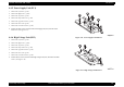
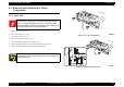

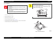
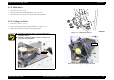
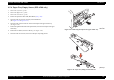
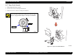


Table Of Contents
- EPSON EPL-6200/EPL-6200L
- Contents
- Product Description
- 1.1 Outline
- 1.2 Basic Specifications
- 1.2.1 Process Specifications
- 1.2.2 Printer Basic Specifications
- 1.2.3 Paper Specification
- 1.2.4 Reliability, Durability, Serviceability
- 1.2.5 Operating Conditions (Including Consumables)
- 1.2.6 Storage and Transport of the Printer Main Unit and Optional Products (Consumables Packaged)
- 1.2.7 Electrical Features
- 1.2.8 Compliance with Standards and Regulations
- 1.2.9 Consumable Components
- 1.3 External Appearance and Parts Name
- 1.4 Controller Specification
- 1.5 Control Panel (EPL-6200)
- 1.6 Control Panel (EPL-6200L)
- 1.7 RAM Expansion
- 1.8 System Requirements (Only for EPL-6200L)
- 1.9 Paper Feed Specifications (Only for EPL-6200L)
- 1.10 Notes on Operation
- 1.11 Status Sheet
- 1.12 Ambient Conditions
- 1.13 Differences in Specifications between Intended Markets
- 1.14 Notes on Installation of Optional Units
- Operating Principles
- 2.1 Overview
- 2.2 Description of Mechanisms
- 2.3 Operating Principles of Electric Circuitry
- Troubleshooting
- 3.1 Overview
- 3.2 Troubleshooting When There is Error Display
- 3.2.1 Fuser warming up problem
- 3.2.2 Fan problem
- 3.2.3 Polygon Motor Error
- 3.2.4 Laser problem
- 3.2.5 High voltage circuit problem
- 3.2.6 Fuser high temperature problem
- 3.2.7 CPU Error
- 3.2.8 Engine Communication Error
- 3.2.9 Fuser low temperature problem
- 3.2.10 Standard RAM Error
- 3.2.11 RAM Error (Slot 0)
- 3.2.12 ROM Checksum Error (Font)
- 3.2.13 ROM Checksum Error (Program)
- 3.2.14 Option ROM Error
- 3.2.15 EEPROM Error
- 3.2.16 Engine Initialization Error
- 3.2.17 Other Hardware Error
- 3.2.18 Software Error
- 3.3 Troubleshooting for Paper Jam
- 3.4 Troubleshooting for Abnormal Operations
- 3.5 Troubleshooting for Electrical Parts
- 3.6 Troubleshooting for Print Quality Problems
- Disassembly and Assembly
- Adjustment
- Maintenance
- Appendix

EPSON EPL-6200/EPL-6200L Revision A
Disassembly and Assembly Removal and Installation of Major Components 152
4.5 Removal and Installation of Major
Components
4.5.1 Fuser Unit
1.
Remove the Left Cover. (p.138)
2.
Remove the Right Cover. (p.139)
3.
Remove the Top Cover. (p.142)
4.
Remove the Paper Exit Cover. (p.143)
5. Disconnect the three connectors.
(See Figure 4-33)
6. Remove the right and left screws (two screws) securing the Fuser Unit.
7. Remove the Fuser Unit by drawing it out toward the rear side.
Figure 4-33. Fuser Unit Removal
Figure 4-34. Installing the Fuser Unit
W A R N I N G
The Fuser Unit remains at hazardous temperature for a certain
period of time even after stop of operation and turning off of the
power. To prevent suffering a burn, be sure to wait after power
turning off until the temperature of the Fuser Unit cools down to a
safe level, and then start working on the printer.
When installing the Fuser Unit, lead the harness as shown in Figure
4-30, and take care not to catch the harness between the Fuser Unit
and the printer body.