
user manual

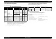
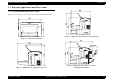

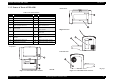
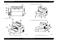

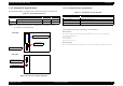
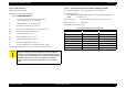
Table Of Contents
- EPSON EPL-6200/EPL-6200L
- Contents
- Product Description
- 1.1 Outline
- 1.2 Basic Specifications
- 1.2.1 Process Specifications
- 1.2.2 Printer Basic Specifications
- 1.2.3 Paper Specification
- 1.2.4 Reliability, Durability, Serviceability
- 1.2.5 Operating Conditions (Including Consumables)
- 1.2.6 Storage and Transport of the Printer Main Unit and Optional Products (Consumables Packaged)
- 1.2.7 Electrical Features
- 1.2.8 Compliance with Standards and Regulations
- 1.2.9 Consumable Components
- 1.3 External Appearance and Parts Name
- 1.4 Controller Specification
- 1.5 Control Panel (EPL-6200)
- 1.6 Control Panel (EPL-6200L)
- 1.7 RAM Expansion
- 1.8 System Requirements (Only for EPL-6200L)
- 1.9 Paper Feed Specifications (Only for EPL-6200L)
- 1.10 Notes on Operation
- 1.11 Status Sheet
- 1.12 Ambient Conditions
- 1.13 Differences in Specifications between Intended Markets
- 1.14 Notes on Installation of Optional Units
- Operating Principles
- 2.1 Overview
- 2.2 Description of Mechanisms
- 2.3 Operating Principles of Electric Circuitry
- Troubleshooting
- 3.1 Overview
- 3.2 Troubleshooting When There is Error Display
- 3.2.1 Fuser warming up problem
- 3.2.2 Fan problem
- 3.2.3 Polygon Motor Error
- 3.2.4 Laser problem
- 3.2.5 High voltage circuit problem
- 3.2.6 Fuser high temperature problem
- 3.2.7 CPU Error
- 3.2.8 Engine Communication Error
- 3.2.9 Fuser low temperature problem
- 3.2.10 Standard RAM Error
- 3.2.11 RAM Error (Slot 0)
- 3.2.12 ROM Checksum Error (Font)
- 3.2.13 ROM Checksum Error (Program)
- 3.2.14 Option ROM Error
- 3.2.15 EEPROM Error
- 3.2.16 Engine Initialization Error
- 3.2.17 Other Hardware Error
- 3.2.18 Software Error
- 3.3 Troubleshooting for Paper Jam
- 3.4 Troubleshooting for Abnormal Operations
- 3.5 Troubleshooting for Electrical Parts
- 3.6 Troubleshooting for Print Quality Problems
- Disassembly and Assembly
- Adjustment
- Maintenance
- Appendix

EPSON EPL-6200/EPL-6200L Revision A
Product Description External Appearance and Parts Name 35
1.3.3 Names of Parts of EPL-6200
Figure 1-12. EPL-6200 Names of Parts 1
Figure 1-13. EPL-6200 Names of Parts 2
Table 1-36. Names of Parts
Symbol Name Symbol Name
1
Control Panel
12
Parallel Interface Connector
2
Manual Feed Tray / Paper Guide
13
Duplex Unit Connector Cover
3
MP Tray / Manual Feed Tray
14
Output Cover
4
Front Cover
15
Output Tray
5
Paper Cassette Front Cover
16
Lower-cassette Unit (option)
Paper Cassette Cover
6
Power Switch
17
Lower-cassette Unit (option)
Paper Cassette
7
Optional RAM Cover
18
Lower-cassette Unit (option)
Feeder Unit
8
Duplex Unit Gear Cover
19
Duplex Unit (option)
9
AC Inlet
20
Duplex Unit (option) Connector
Cover
10
Type-B Interface Slot Cover
21
Duplex Unit (option) Cover 1
11
USB Interface Connector
22
Duplex Unit (option) Cover 2
<Top View>
<Front View>
<Right Side View>
<Left Side View>