
user manual
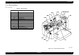
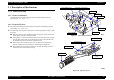
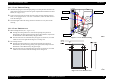
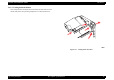

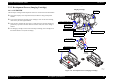
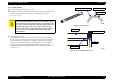
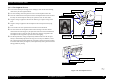
Table Of Contents
- EPSON EPL-6200/EPL-6200L
- Contents
- Product Description
- 1.1 Outline
- 1.2 Basic Specifications
- 1.2.1 Process Specifications
- 1.2.2 Printer Basic Specifications
- 1.2.3 Paper Specification
- 1.2.4 Reliability, Durability, Serviceability
- 1.2.5 Operating Conditions (Including Consumables)
- 1.2.6 Storage and Transport of the Printer Main Unit and Optional Products (Consumables Packaged)
- 1.2.7 Electrical Features
- 1.2.8 Compliance with Standards and Regulations
- 1.2.9 Consumable Components
- 1.3 External Appearance and Parts Name
- 1.4 Controller Specification
- 1.5 Control Panel (EPL-6200)
- 1.6 Control Panel (EPL-6200L)
- 1.7 RAM Expansion
- 1.8 System Requirements (Only for EPL-6200L)
- 1.9 Paper Feed Specifications (Only for EPL-6200L)
- 1.10 Notes on Operation
- 1.11 Status Sheet
- 1.12 Ambient Conditions
- 1.13 Differences in Specifications between Intended Markets
- 1.14 Notes on Installation of Optional Units
- Operating Principles
- 2.1 Overview
- 2.2 Description of Mechanisms
- 2.3 Operating Principles of Electric Circuitry
- Troubleshooting
- 3.1 Overview
- 3.2 Troubleshooting When There is Error Display
- 3.2.1 Fuser warming up problem
- 3.2.2 Fan problem
- 3.2.3 Polygon Motor Error
- 3.2.4 Laser problem
- 3.2.5 High voltage circuit problem
- 3.2.6 Fuser high temperature problem
- 3.2.7 CPU Error
- 3.2.8 Engine Communication Error
- 3.2.9 Fuser low temperature problem
- 3.2.10 Standard RAM Error
- 3.2.11 RAM Error (Slot 0)
- 3.2.12 ROM Checksum Error (Font)
- 3.2.13 ROM Checksum Error (Program)
- 3.2.14 Option ROM Error
- 3.2.15 EEPROM Error
- 3.2.16 Engine Initialization Error
- 3.2.17 Other Hardware Error
- 3.2.18 Software Error
- 3.3 Troubleshooting for Paper Jam
- 3.4 Troubleshooting for Abnormal Operations
- 3.5 Troubleshooting for Electrical Parts
- 3.6 Troubleshooting for Print Quality Problems
- Disassembly and Assembly
- Adjustment
- Maintenance
- Appendix

EPSON EPL-6200/EPL-6200L Revision A
Operating Principles Description of Mechanisms 74
2.2 Description of Mechanisms
2.2.1 Print Head (PH)
2.2.1.1 Entire Constitution
Scanning with the laser beam coming out of the Print Head is performed by the
polygon motor.
(See “Figure 2-7”)
2.2.1.2 Exposure Process
The laser beam from the print head creates an electrostatic latent image on the OPC
drum surface.
(See “Figure 2-8”)
The following control is performed in order to find the appropriate timing to print
the image.
When the printer receives the PRINT signal, the polygon motor and the main
motor operate, and paper feeding is started.
Upon passage of a specified period of time after the front end of the fed sheet
turns the paper feed sensor ON (TOD signal), the main control board sends
the VIDEO signal to the print head, and printing starts.
When moving on from the first line to the second line, the print starting
position is shifted down by delaying the VIDEO signal sending time
The Print Head incorporates the SOS sensor to unify the timing of the laser
emission for every line of main scanning.
Figure 2-7. Print Head Constitution
Figure 2-8. Exposure Process
Semi-conductor Laser
G1 Lens
G2 Lens
1st Mirror
SOS (Start of Scan) Sensor
Polygon Mirror
SOS Mirror
2nd Mirror
OPC Drum
Polygon Motor
Print Head Unit
Laser Diode
SOS (Start of Scan)
Sensor