
user manual

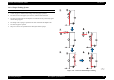
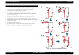
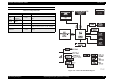
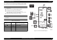


Table Of Contents
- EPSON EPL-6200/EPL-6200L
- Contents
- Product Description
- 1.1 Outline
- 1.2 Basic Specifications
- 1.2.1 Process Specifications
- 1.2.2 Printer Basic Specifications
- 1.2.3 Paper Specification
- 1.2.4 Reliability, Durability, Serviceability
- 1.2.5 Operating Conditions (Including Consumables)
- 1.2.6 Storage and Transport of the Printer Main Unit and Optional Products (Consumables Packaged)
- 1.2.7 Electrical Features
- 1.2.8 Compliance with Standards and Regulations
- 1.2.9 Consumable Components
- 1.3 External Appearance and Parts Name
- 1.4 Controller Specification
- 1.5 Control Panel (EPL-6200)
- 1.6 Control Panel (EPL-6200L)
- 1.7 RAM Expansion
- 1.8 System Requirements (Only for EPL-6200L)
- 1.9 Paper Feed Specifications (Only for EPL-6200L)
- 1.10 Notes on Operation
- 1.11 Status Sheet
- 1.12 Ambient Conditions
- 1.13 Differences in Specifications between Intended Markets
- 1.14 Notes on Installation of Optional Units
- Operating Principles
- 2.1 Overview
- 2.2 Description of Mechanisms
- 2.3 Operating Principles of Electric Circuitry
- Troubleshooting
- 3.1 Overview
- 3.2 Troubleshooting When There is Error Display
- 3.2.1 Fuser warming up problem
- 3.2.2 Fan problem
- 3.2.3 Polygon Motor Error
- 3.2.4 Laser problem
- 3.2.5 High voltage circuit problem
- 3.2.6 Fuser high temperature problem
- 3.2.7 CPU Error
- 3.2.8 Engine Communication Error
- 3.2.9 Fuser low temperature problem
- 3.2.10 Standard RAM Error
- 3.2.11 RAM Error (Slot 0)
- 3.2.12 ROM Checksum Error (Font)
- 3.2.13 ROM Checksum Error (Program)
- 3.2.14 Option ROM Error
- 3.2.15 EEPROM Error
- 3.2.16 Engine Initialization Error
- 3.2.17 Other Hardware Error
- 3.2.18 Software Error
- 3.3 Troubleshooting for Paper Jam
- 3.4 Troubleshooting for Abnormal Operations
- 3.5 Troubleshooting for Electrical Parts
- 3.6 Troubleshooting for Print Quality Problems
- Disassembly and Assembly
- Adjustment
- Maintenance
- Appendix

EPSON EPL-6200/EPL-6200L Revision A
Operating Principles Description of Mechanisms 91
2.2.9.2 Driving of Duplex Unit
The Duplex Unit is driven as follows: the paper after printing on one side is fed into the
Output Tray once and when the tail end of the paper has left the guide behind the paper
eject roller, the paper eject roller starts rotating to transport the paper into the Duplex
Unit.
(See “Figure 2-30”)
The paper is transported into the printer body by the duplex unit transport motor.
With the Duplex Unit installed, the paper eject roller is separated from the drive on the
printer body and is driven by the inversion motor in the Duplex Unit.
(See “Figure 2-31”)
Figure 2-30. Driving of Duplex Unit
Figure 2-31. Driving of Inversion Motor
Duplex Unit Inversion Motor (M5)
Transport Roller 1
Transport Roller 2
Duplex Unit Drive
Motor (M4)