
user manual

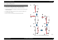
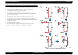
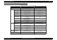
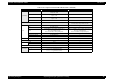
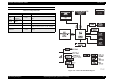
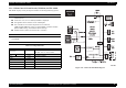


Table Of Contents
- EPSON EPL-6200/EPL-6200L
- Contents
- Product Description
- 1.1 Outline
- 1.2 Basic Specifications
- 1.2.1 Process Specifications
- 1.2.2 Printer Basic Specifications
- 1.2.3 Paper Specification
- 1.2.4 Reliability, Durability, Serviceability
- 1.2.5 Operating Conditions (Including Consumables)
- 1.2.6 Storage and Transport of the Printer Main Unit and Optional Products (Consumables Packaged)
- 1.2.7 Electrical Features
- 1.2.8 Compliance with Standards and Regulations
- 1.2.9 Consumable Components
- 1.3 External Appearance and Parts Name
- 1.4 Controller Specification
- 1.5 Control Panel (EPL-6200)
- 1.6 Control Panel (EPL-6200L)
- 1.7 RAM Expansion
- 1.8 System Requirements (Only for EPL-6200L)
- 1.9 Paper Feed Specifications (Only for EPL-6200L)
- 1.10 Notes on Operation
- 1.11 Status Sheet
- 1.12 Ambient Conditions
- 1.13 Differences in Specifications between Intended Markets
- 1.14 Notes on Installation of Optional Units
- Operating Principles
- 2.1 Overview
- 2.2 Description of Mechanisms
- 2.3 Operating Principles of Electric Circuitry
- Troubleshooting
- 3.1 Overview
- 3.2 Troubleshooting When There is Error Display
- 3.2.1 Fuser warming up problem
- 3.2.2 Fan problem
- 3.2.3 Polygon Motor Error
- 3.2.4 Laser problem
- 3.2.5 High voltage circuit problem
- 3.2.6 Fuser high temperature problem
- 3.2.7 CPU Error
- 3.2.8 Engine Communication Error
- 3.2.9 Fuser low temperature problem
- 3.2.10 Standard RAM Error
- 3.2.11 RAM Error (Slot 0)
- 3.2.12 ROM Checksum Error (Font)
- 3.2.13 ROM Checksum Error (Program)
- 3.2.14 Option ROM Error
- 3.2.15 EEPROM Error
- 3.2.16 Engine Initialization Error
- 3.2.17 Other Hardware Error
- 3.2.18 Software Error
- 3.3 Troubleshooting for Paper Jam
- 3.4 Troubleshooting for Abnormal Operations
- 3.5 Troubleshooting for Electrical Parts
- 3.6 Troubleshooting for Print Quality Problems
- Disassembly and Assembly
- Adjustment
- Maintenance
- Appendix

EPSON EPL-6200/EPL-6200L Revision A
Operating Principles Operating Principles of Electric Circuitry 95
COMPARISON OF EPL-6200 WITH EPL-6100
Table 2-10. Comparison of EPL-6200 with EPL-6100
Device EPL-6100 EPL-6200
CPU TMPR4955AF-200 TMPR4955BFG-200
ASIC
DLC: E05B96BA
Memory, I/O integrated controller, USB
←
Memory
Onboard MASK ROM None ←
Standard ROM-DIMM
1 slot. +3.3V DIMM.
IPL, Code, Font, SDRAM
1 slot. +3.3V DIMM. IPL, Code, Font, PS, SDRAM
Address A23 expanded
Standard ROM constitution
at initial production
Code: Flash 8/16 Mbit (x16) 2 pieces
Font: MASK 32 Mbit (x32) 1 piece
Code, Font, PS:1 6 MB
Flash 64 Mbit (x16) 2 pieces
Standard ROM constitution
by steady production
Code, Font: 8 MB
Mask 64 Mbit (x32) 1 piece
Code, Font, PS: 16 MB
Mask128 Mbit (x32) 1 piece
Font type BitStream AGFA
Option ROM-DIMM
1 slot for local language and extension ROM,
ConvROM (Board C)
+3.3V DIMM
None
Standard SDRAM
Mounted on the DIMM for code.
8 MB: 64 Mbit (x32) 1 piece
←
SDRAM-DIMM
1slot. Newly employed 90-pin. 2 / 4 pieces
16, 32, 64, 128 MB
←
EEPROM 128 Kbits, serial type, for storage of printer settings. M95128. ←
CSIC Not supported Supported (Main firmware control)
Host I/F
Parallel interface
IEEE1284 compliance, B type connector.
Separate IF board connected with FPC. Transceiver,
Protection diode: None
←
IF board connected with FPC.
(Only parallel)
USB
USB 1.1, B-type connector
Separate IF board connected with FPC.
←
Connected with harness to MAIN board.
Serial interface
None
UACLK: None
←
Onboard Network
Not mounted. Mounted at soft development.
DL10022.
←
Control Panel Control Panel Unit
New-type controller panel.
No LCD, 3 switches, 6 LEDs
LED driver: 74LCX07. FPC connection.
←
Harness connection.
Video I/F MLT NC-L601H ←
Mechanical Controller Integrated. (No Video I/F connector) ←